Illumination device

Inactive Publication Date: 2010-12-30
FOXSEMICON INTEGRATED TECH INC
View PDF3 Cites 16 Cited by
  • Summary
  • Abstract
  • Description
  • Claims
  • Application Information

AI Technical Summary

Problems solved by technology

However, considerable heat is generated by the LED, which, if exceeding a certain limit, such as 120° C., can detrimentally affect working voltage, wavelength and luminous intensity of the LED.
Nevertheless, hot air between the fins flows very slowly, so considerable heat remains around the LED.
If a

Method used


Image

  • Illumination device
  • Illumination device
  • Illumination device

Examples


first embodiment

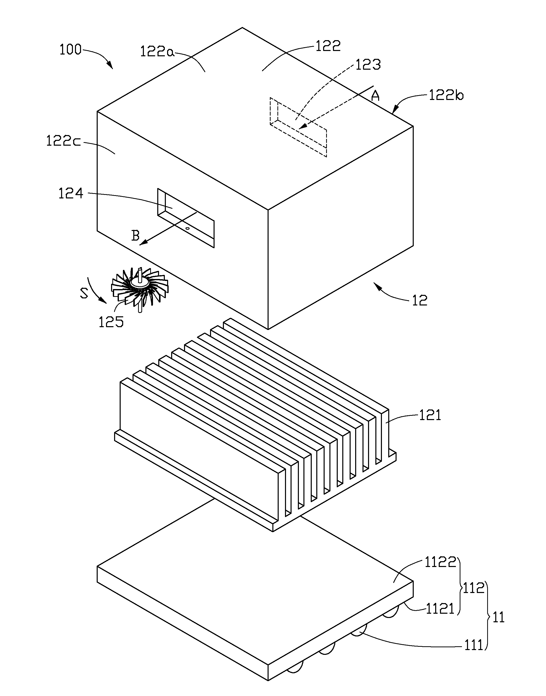
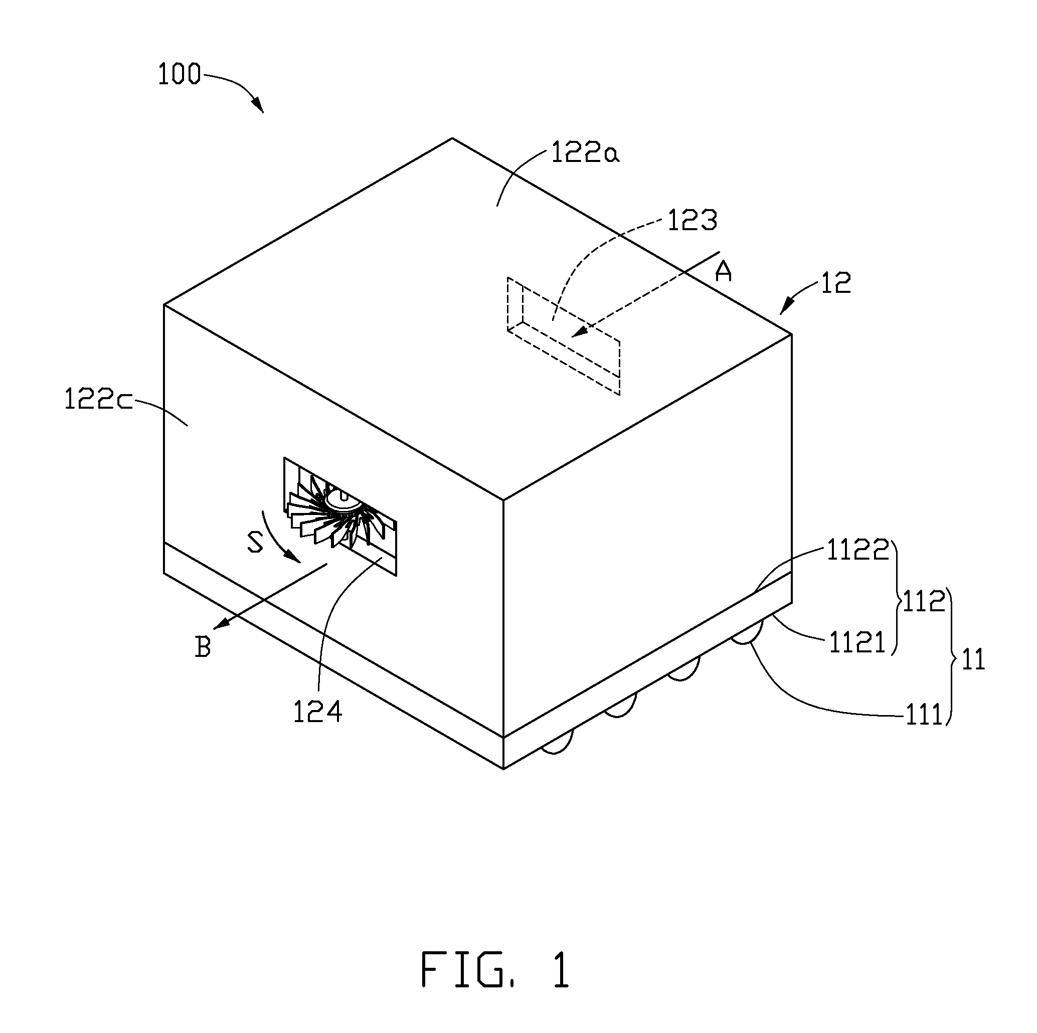
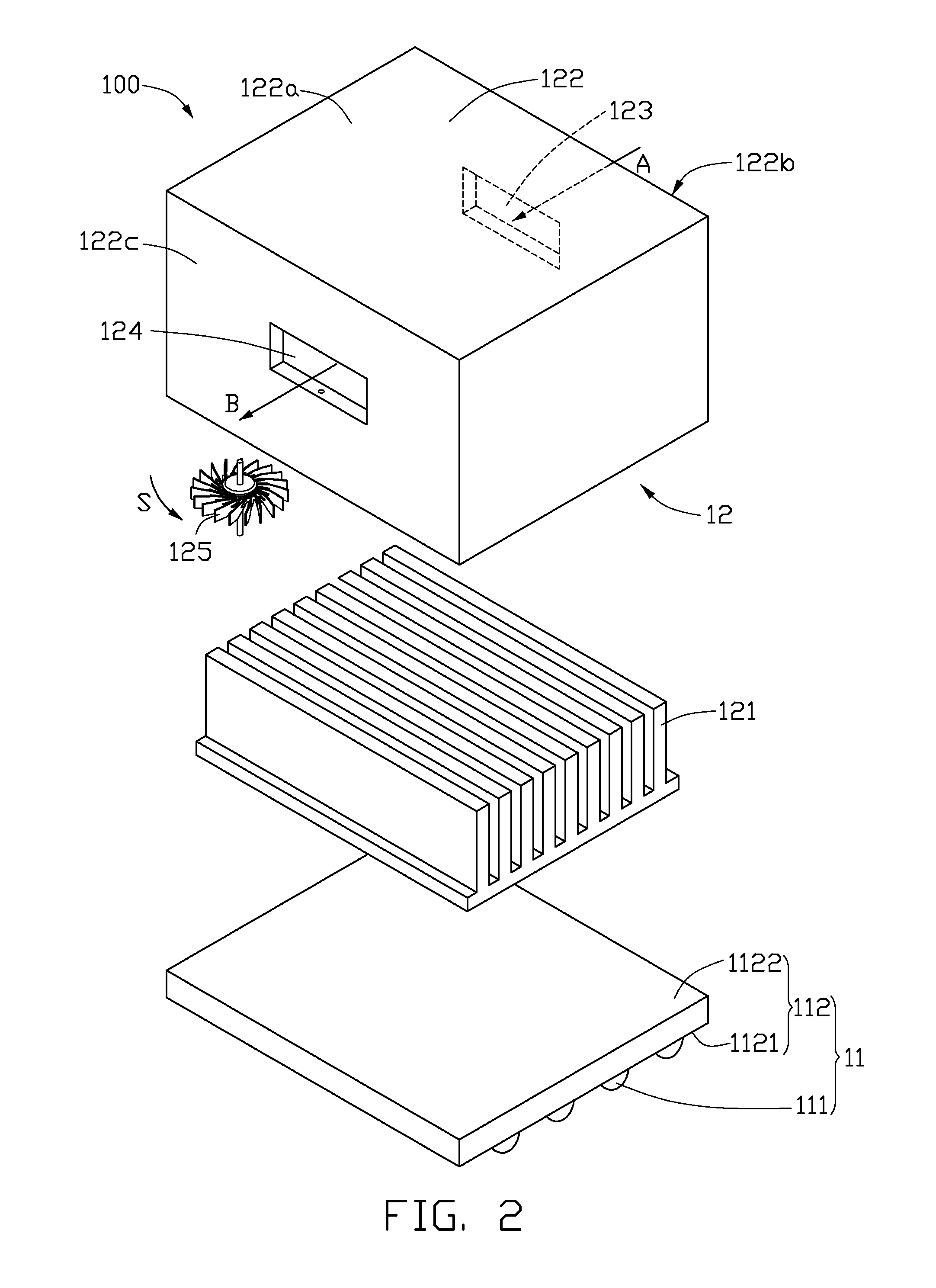
[0014]Referring to FIGS. 1-2, an illumination device 100 according to the present disclosure includes a light source 11 and a heat dissipation device 12. The light source 11 includes a plurality of LEDs 111 and a base 112. The base 112 includes a first surface 1121, and a second surface 1122 opposite thereto. The LEDs 111 are mounted on the first surface 1121 of the base 112, and electrically connected to the base 112.

[0015]The heat dissipation device 12 is disposed on the second surface 1122 of the base 112 and thermally connected to the base 112. The heat dissipation device 12 includes a plurality of fins 121, a hollow shell 122 and a fan 125. The fins 121 are received in the hollow shell 122, and thermally connected to the second surface 1122 of the base 112. The hollow shell 122 is detachably fixed on the second surface 1122 of the base 112. The hollow shell 122 includes a top plate 122a, a first sidewall 122b and a second sidewall 122c. Both the first sidewall 122b and the seco...

second embodiment

[0017]Referring to FIG. 3, an illumination device 200 according to the present disclosure includes a light source 21 and a heat dissipation device 22. The light source 21 includes a plurality of LEDs 211 and a base 212. The base 212 includes a first surface 2121, and a second surface 2122 opposite thereto. The LEDs 211 are mounted on the first surface 2121 of the base 212, and electrically connected to the base 212.

[0018]The heat dissipation device 22 is disposed on the second surface 2122 of the base 212 and thermally connected to the base 212. The heat dissipation device 22 includes a plurality of fins 221, a hollow shell 222 and a fan 225. The fins 221 are received in the hollow shell 222, and thermally connected to the second surface 2122 of the base 212. The hollow shell 222 is detachably fixed on the second surface 2122 of the base 212. The hollow shell 222 includes a top plate 222a, a first sidewall 222b and a second sidewall 222c. Both the first sidewall 222b and the second ...

third embodiment

[0021]Referring to FIG. 4, an illumination device 300 according to the present disclosure includes a light source 31 and a heat dissipation device 32. The light source 31 includes a plurality of LEDs 311 and a base 312. The base 312 includes a first surface 3121, and a second surface 3122 opposite to the first surface 3121. The LEDs 311 are mounted on the first surface 3121 of the base 312, and electrically connected to the base 312.

[0022]The heat dissipation device 32 is disposed on the second surface 3122 of the base 312 and thermally connected to the base 312. The heat dissipation device 32 includes a plurality of fins 321, a hollow shell 322 and a fan 325. The fins 321 are received in the hollow shell 322, and thermally connected to the second surface 3122 of the base 312. The hollow shell 322 is detachably fixed on the second surface 3122 of the base 312. The hollow shell 322 includes a top plate 322a, a first sidewall 322b and a second sidewall 322c. Both the first sidewall 32...


PUM


Abstract

An illumination device includes a light source and a heat dissipation device. The light source includes a base and at least a light emitting diode on the base. The heat dissipation device includes a fan for dissipating heat from the light source, and a hollow shell. The hollow shell has an inlet and an outlet defined thereon. The fan is located on the hollow shell, and the airflow from the fan is parallel to a rotation plane of the fan. In operation, air is impelled from the hollow shell by the fan, and heat from the light source is evacuated by airflow from the inlet to the outlet, and air pressure in the shell is reduced. Cool air flows into the hollow shell through the inlet.

Description

BACKGROUND[0001]1. Technical Field[0002]The present disclosure relates to an illumination device, and particularly, to a light emitting diode (LED) illumination device.[0003]2. Description of Related Art[0004]LEDs are extensively applied due to high brightness, low working voltage, low power consumption, compatibility with integrated circuitry, simple driving operation, long lifetime and other factors.[0005]However, considerable heat is generated by the LED, which, if exceeding a certain limit, such as 120° C., can detrimentally affect working voltage, wavelength and luminous intensity of the LED. Accordingly, heat dissipating fins are often attached to the bottom of the LED light source of the illumination device in a manifold configuration. The generated heat is conducted from the LED toward the fins, and dissipated into the surroundings by natural convection. Nevertheless, hot air between the fins flows very slowly, so considerable heat remains around the LED. If an electric fan ...

Claims


Application Information

Patent Timeline
IPC IPC(8): F21S4/00F21V29/00
CPCF21K9/00F21S2/005F21V29/02F21V29/763F21Y2105/001F21V29/677F21Y2101/02F21Y2105/10F21Y2115/10
Inventor LAI, CHIH-MINGLIU, YU-PIN
Owner FOXSEMICON INTEGRATED TECH INC
Why Eureka
Try Eureka