
Percutaneous system for dynamic spinal stabilization

a dynamic stabilization and percutaneous technology, applied in the field of spine disorders, can solve the problems of reducing recovery time and achieve the effects of reducing the amount of trauma to the patient, reducing the recovery time, and effective stabilizing two or more adjacent vertebra

Active Publication Date: 2010-12-30
NEUROPRO TECH
View PDF25 Cites 42 Cited by
  • Summary
  • Abstract
  • Description
  • Claims
  • Application Information

AI Technical Summary

Benefits of technology

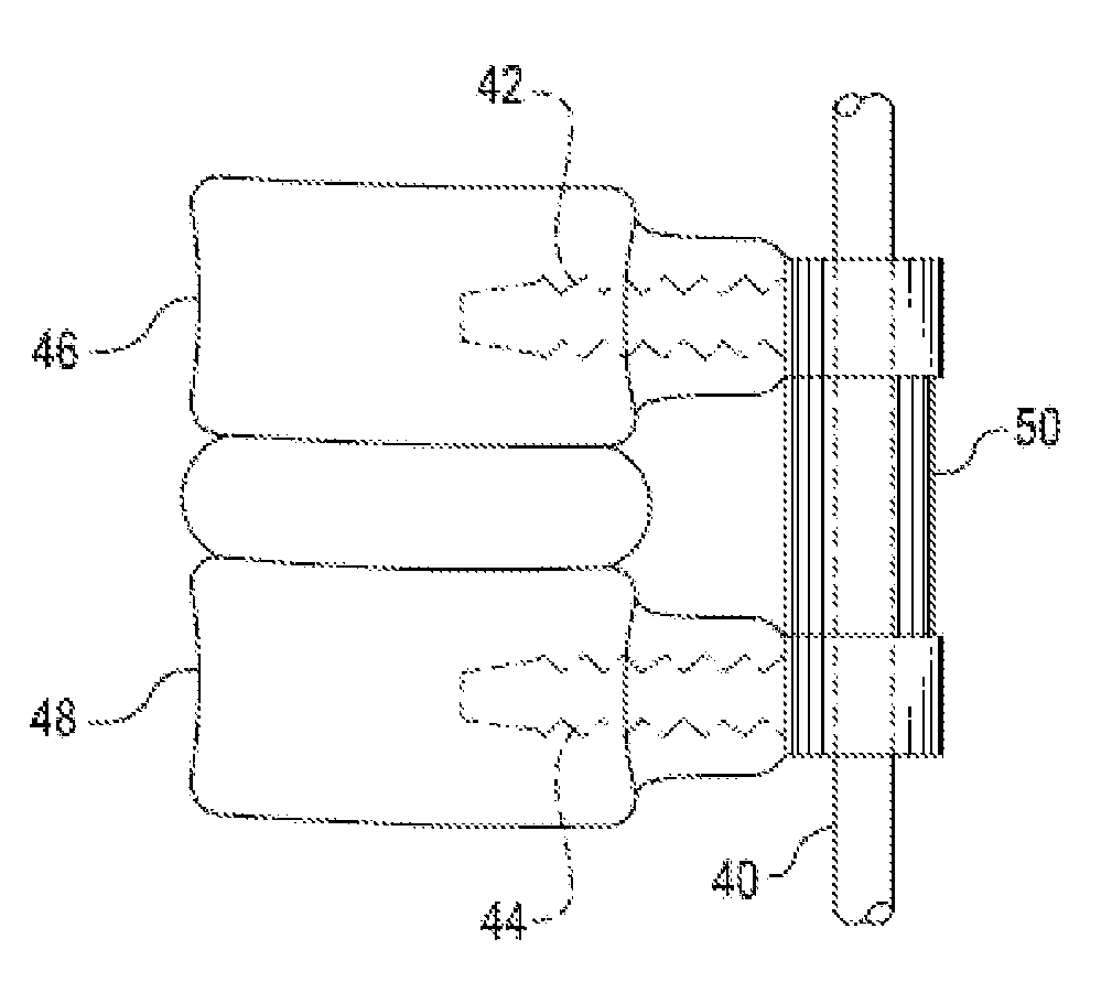
The present invention provides bone anchoring assemblies and placement systems for dynamic stabilization of the spine using minimally invasive techniques. These assemblies and systems allow for stabilization of two or more adjacent vertebrae, reducing trauma to the patient and recovery time. The invention includes a bone engaging member, a receiving member, and a retaining member, which can be easily positioned in the spine using small incisions. The invention also provides methods for transferring an elongated stabilization member percutaneously between pedicle screws. Overall, the invention allows for effective stabilization of the spine with reduced recovery time and minimal damage to the patient.

Problems solved by technology

This reduces the amount of trauma to the patient and decreases the recovery time.

Method used


Image

  • Percutaneous system for dynamic spinal stabilization
  • Percutaneous system for dynamic spinal stabilization
  • Percutaneous system for dynamic spinal stabilization

Examples


Embodiment Construction

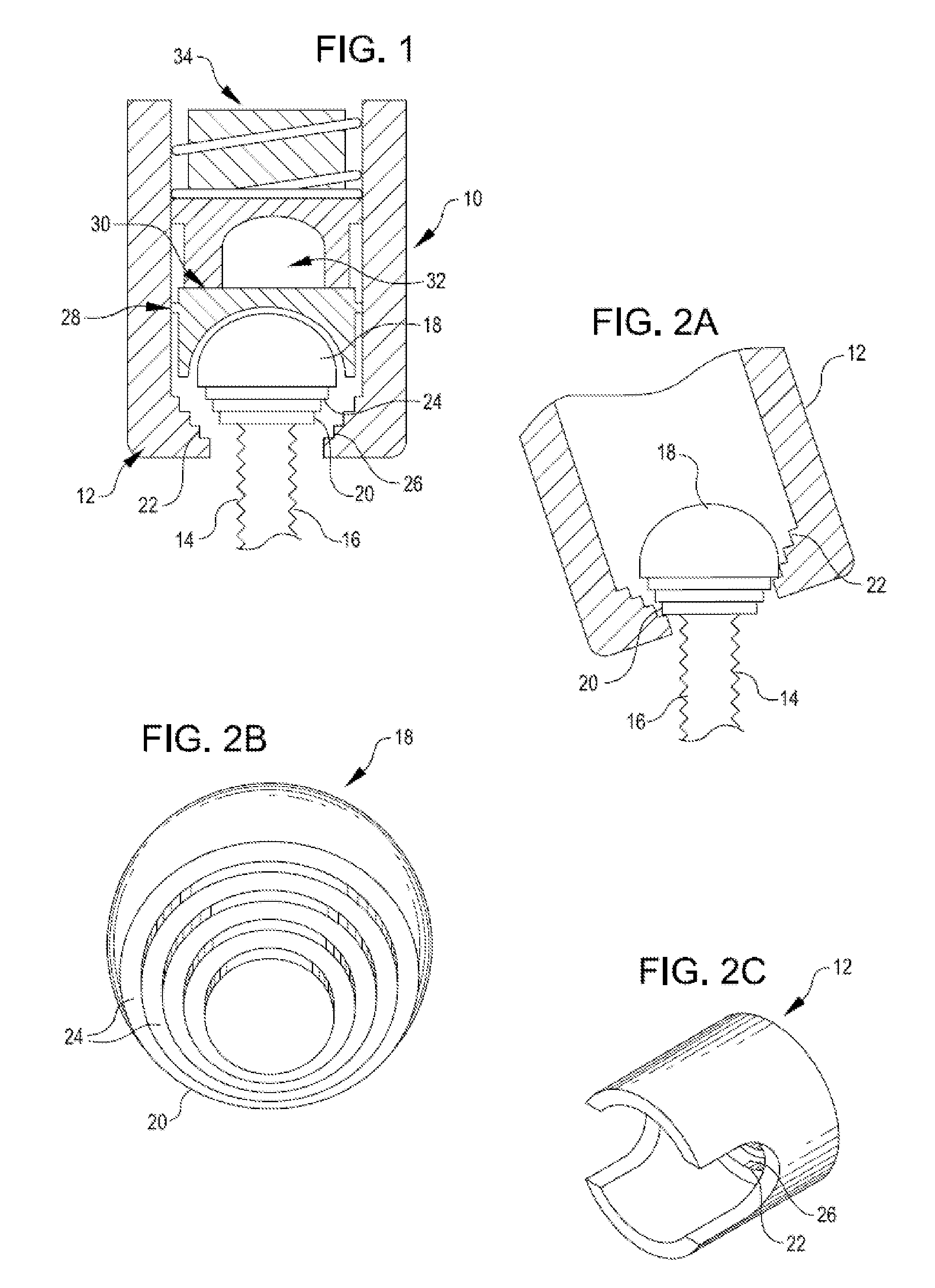
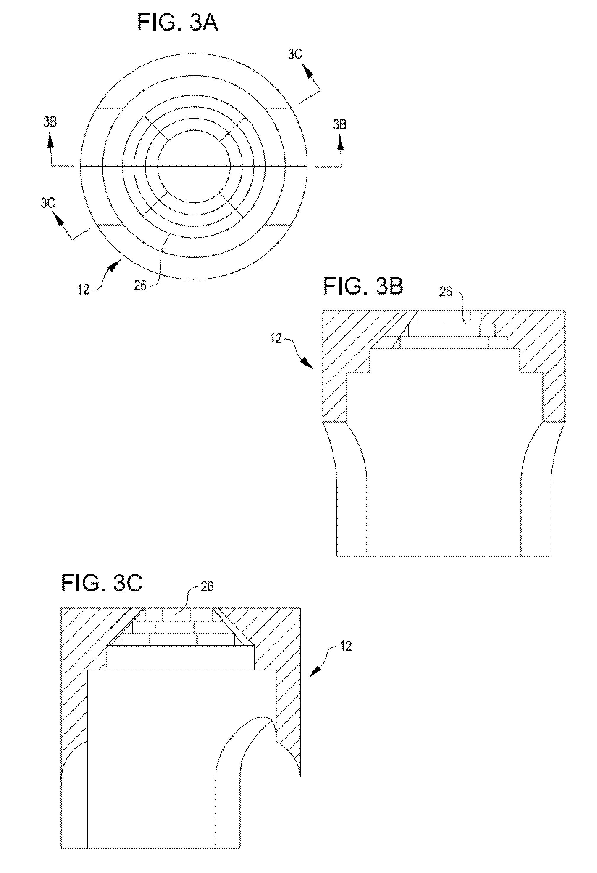
[0031]In one embodiment, illustrated in FIGS. 1 and 2A-C, a bone anchoring assembly 10 is provided that comprises a receiving member 12 that is configured to receive and retain a spinal stabilization member, such as a rod or cord, to be extended between two or more vertebrae, together with a bone engaging member 14. Bone engaging member 14 comprises a generally elongated shank portion 16 and an enlarged head portion 18 located at a proximal end of shank portion 16. Shank portion 16 generally tapers towards its distal end and may be threaded to facilitate engagement in a bone, such as a vertebra. In the embodiment illustrated herein, shank portion 16 is threaded, however those of skill in the art will appreciate that other designs of shank portions may be effectively employed in the systems disclosed herein. Receiving member 12 is sized to receive and movably retain enlarged head portion 18 of bone engaging member 14 and may, for example, be tulip-shaped. Enlarged head portion 18 is ...


PUM


Abstract

Bone anchoring assemblies for use with minimally invasive surgery (MIS) techniques for dynamic stabilization of the spine, together with placement systems for use in such techniques are provided.

Description

FIELD OF THE INVENTION[0001]The present invention relates generally to methods and systems for the treatment of disorders of the spine, and more specifically to methods and systems for dynamic stabilization of the spine.BACKGROUND OF THE INVENTION[0002]Lower back pain is one of the most common, and one of the most expensive, disorders afflicting industrialized societies. Conservative treatments include rest, application of ice or heat, exercise, physical therapy, narcotics, steroids and weight control. If these treatments are insufficient to control pain and allow return to normal activity, surgical treatment may be required in which all or part of one or more degenerated, ruptured or otherwise failing discs is removed. This is followed by insertion of an interbody device, for example an artificial disc or fusion implant, and / or fusion of adjacent vertebrae. While fusion surgery is effective in a majority of cases, it has several disadvantages including a reduced range of spinal mot...

Claims


Application Information

Patent Timeline
Patent Type & Authority Applications(United States)
IPC IPC(8): A61B17/70A61B17/86
CPCA61B17/7008A61B17/7085A61B17/7037
Inventor REMINGTON, BENJAMIN J.BAKER, DANIEL R.KIRKWOOD, KEITH W.
Owner NEUROPRO TECH
Learn More