Centrifugal compressor

Inactive Publication Date: 2010-02-11
HITACHI PLANT TECH LTD
View PDF8 Cites 25 Cited by
  • Summary
  • Abstract
  • Description
  • Claims
  • Application Information

AI Technical Summary

Benefits of technology

[0007]An object of the present invention is to provide a centrifugal compressor that can be stably o

Problems solved by technology

This results in a fluid force (hereinafter referred to as a “destabilizing fluid force) destabilizing the rotor.
In the worst case, the destabilizing fluid force causes the rotor to vibrate unstably.
In particular, if the rotor rotates at high speed or there is a high differential pressure between the seal inlet and outlet, t

Method used


Image

  • Centrifugal compressor
  • Centrifugal compressor
  • Centrifugal compressor

Examples


Example

[0019]An embodiment of the present invention will be described below with reference to the drawings.

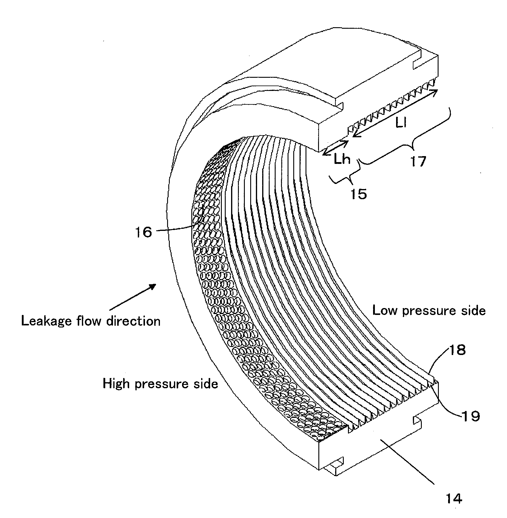
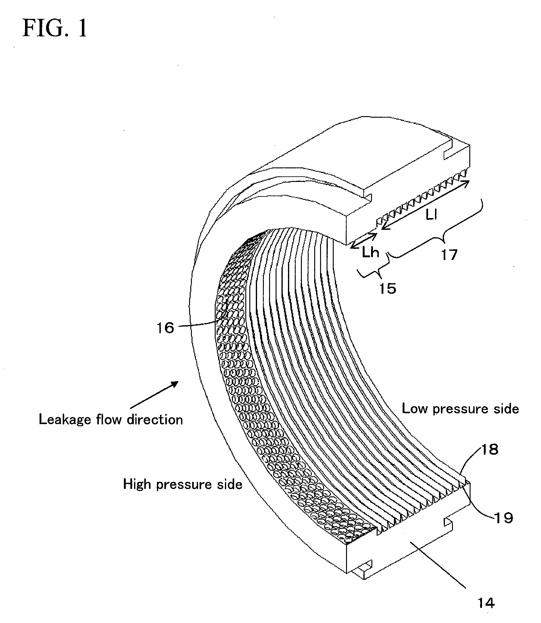
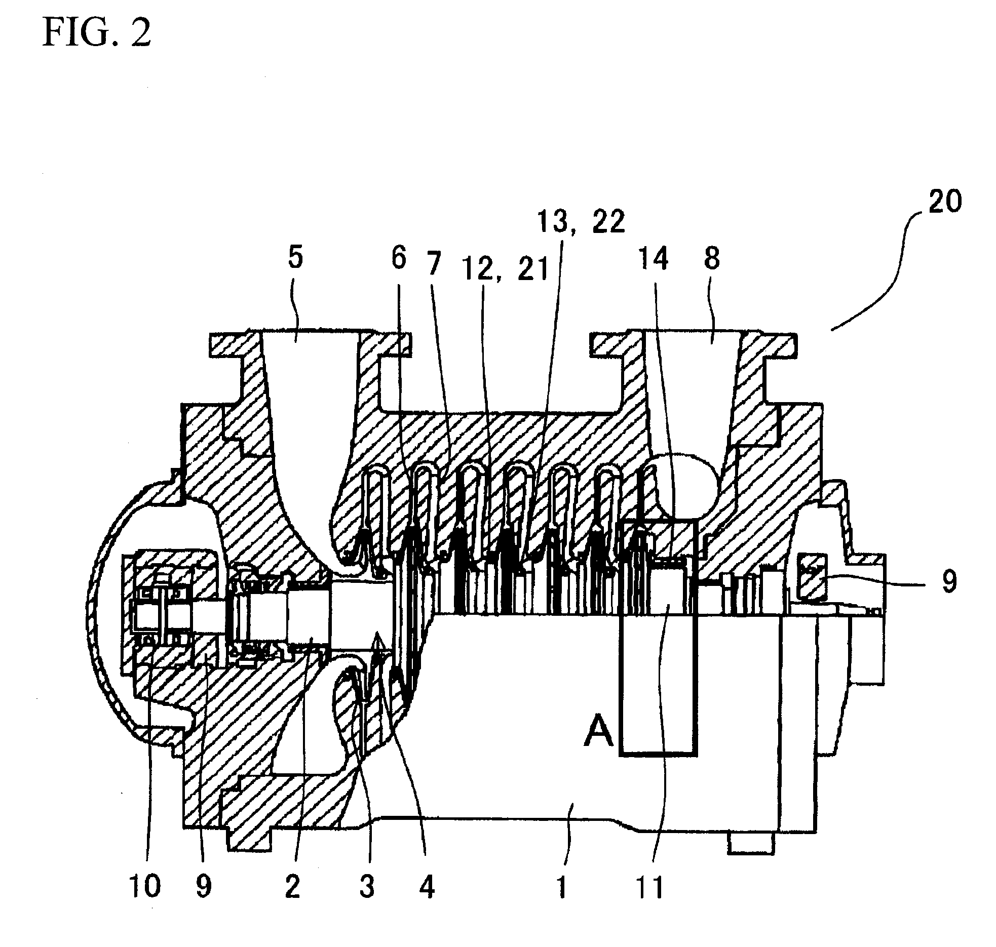
[0020]FIG. 1 is a perspective view showing, in detail, the structure of a balance piston seal 14 in an embodiment of a centrifugal compressor 20 according to the present invention. An illustrated damper seal is a hole pattern seal 15 made up of a large number of holes 16. FIG. 2 shows the general structure of a centrifugal compressor 20 according to the present invention. FIG. 3 is a diagram showing an area A in FIG. 2.

[0021]In FIG. 2, the centrifugal compressor 20 includes a casing 1 (stationary member), a rotating shaft 2 rotatably provided in the casing 1, and a rotor 4 having a multi-stage (in FIG. 2, seven-stage) impeller 3 installed on the rotating shaft 2. The casing 1 includes a suction channel 5 through which gas is introduced into a first stage of the impeller 3, a diffuser 6 that converts kinetic energy from each stage of the impeller 3 into pressure energy, a return channe...


PUM


Abstract

The present invention provides a centrifugal compressor that inhibits possible leakage while reducing a destabilizing fluid force generated in a seal to prevent the possible instable vibration of a rotor. The centrifugal compressor includes a casing, a rotor rotatably installed in the casing and having an impeller, and seals provided in the clearance between the casing and the rotor to prevent a fluid from leaking through the clearance from a high pressure side to a low pressure side. The rotor rotates to compress gas. For example, the balance piston seal is composed of a damper seal with a plurality of holes and a labyrinth seal with an annular parallel groove; the damper seal and the labyrinth seal are continuously provided. The damper seal is disposed on the high pressure side in a leakage flow direction. The labyrinth seal is disposed on the low pressure side in the leakage flow direction.

Description

BACKGROUND OF THE INVENTION[0001]The present invention relates to a seal structure for a centrifugal compressor, and is suitable particularly for preventing unstable vibration of a rotor during a high-speed, high-pressure operation.[0002]Centrifugal compressors compressing gas such as air are widely utilized for various machines. Inside of a casing of a centrifugal compressor, a rotating shaft with an impeller installed thereon is rotatably supported by bearings. Gas sucked through a suction port is compressed by rotation of the impeller and discharged through a discharge port. The gas compressed by the impeller is sealed by an impeller eye seal of an impeller eye, an inter-stage seal between stages of the impeller, and a balance piston seal provided in a last stage.[0003]A labyrinth seal and a damper seal are known as conventional seal structures. As shown in a sectional view of any impeller stage in a centrifugal compressor in FIG. 1 of JP Published Patent Application No. 6-249186...

Claims


Application Information

Patent Timeline
IPC IPC(8): F04D29/08
CPCF16J15/4472F04D29/102F04D29/0516
Inventor MAGARA, YOHEIYAMAGUCHI, KAZUYUKIKUWANO, TETSUYAMIURA, HARUOTAKAHASHI, NAOHIKO
Owner HITACHI PLANT TECH LTD
Why Eureka
Try Eureka