Vehicle motion control device
a technology of motion control device and steering wheel, which is applied in the field of vehicle motion control device, can solve the problems of side slip of the outside wheel and the front inside wheel, the front inside wheel to skid as well as the outside wheel, and achieve the effect of suppressing the reduction of steeringability
- Summary
- Abstract
- Description
- Claims
- Application Information
AI Technical Summary
Benefits of technology
Problems solved by technology
Method used
Image

Examples
first embodiment
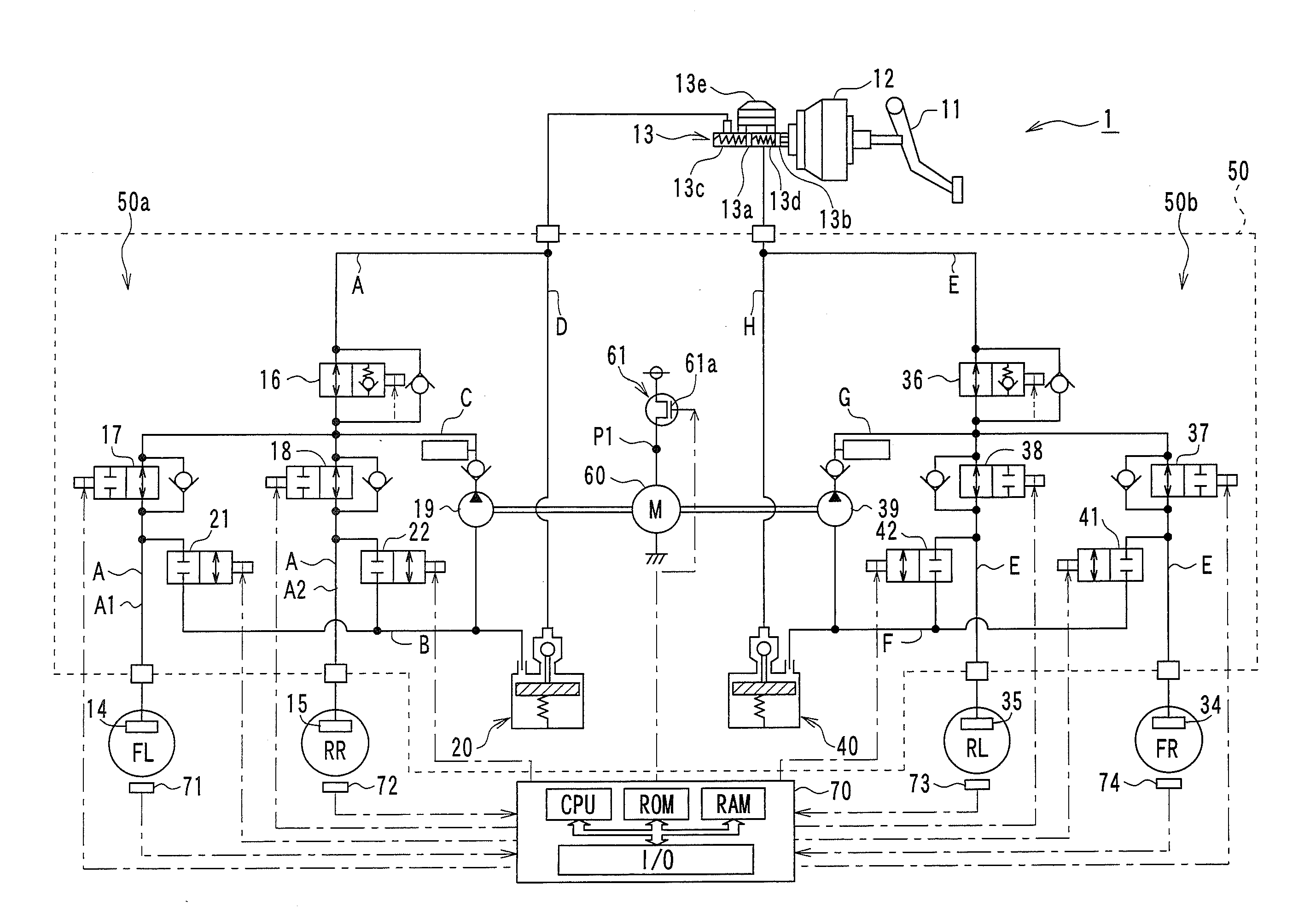
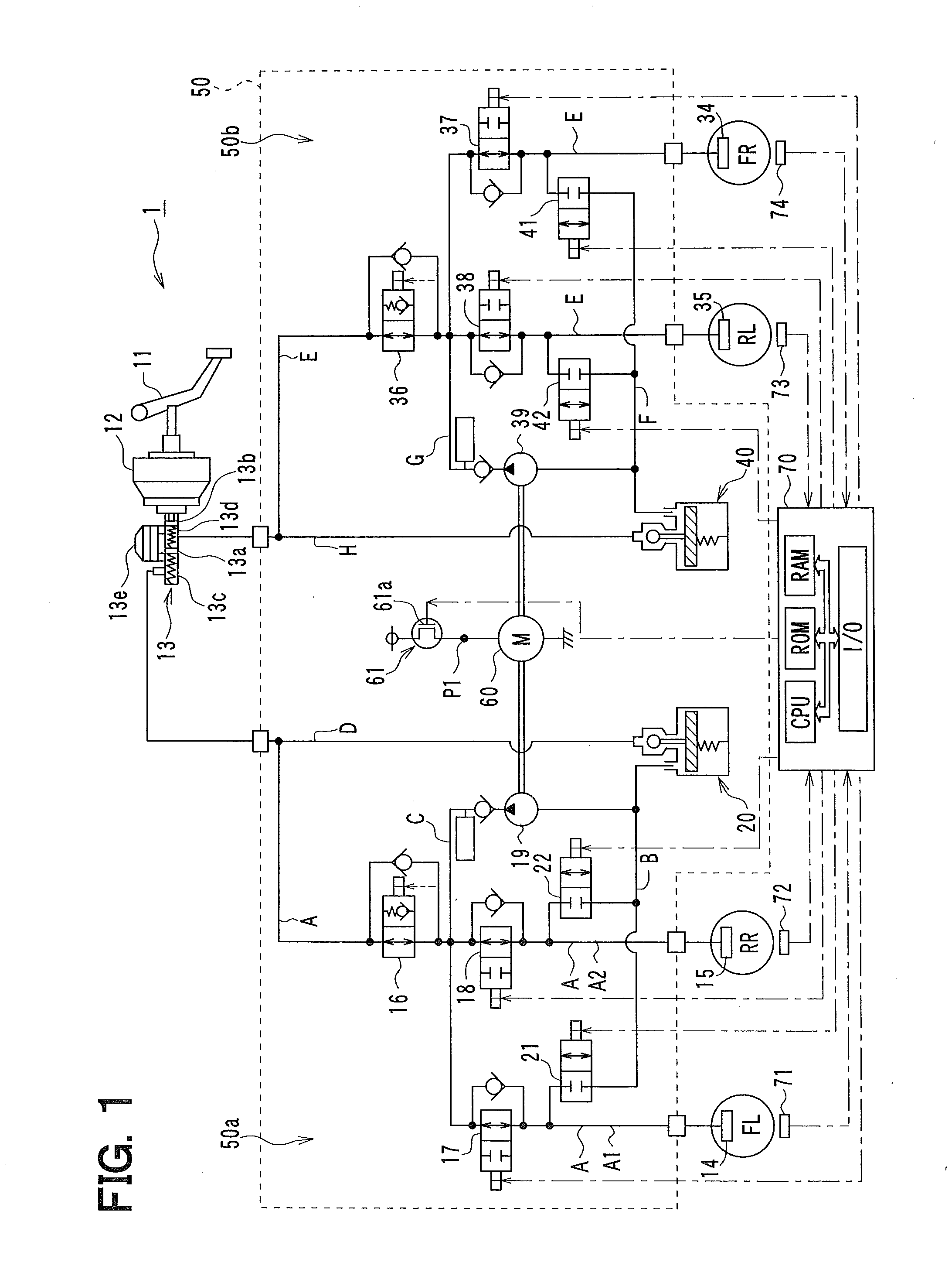
[0033]A first embodiment of the present invention will now be described. FIG. 1 is a diagram showing the overall structure of a brake control system 1 for a vehicle that realizes a vehicle motion control according to a first embodiment of the present invention. In the first embodiment, a case will be described in which an anti-lateral overturn control is performed as the vehicle motion control.
[0034]With reference to FIG. 1, when a driver depresses a brake pedal 11, the depression force is boosted by a servo unit 12, and pushes master pistons 13a, 13b located in a master cylinder 13. As a result, a same master cylinder pressure is generated in a primary chamber 13c and a secondary chamber 13d defined by the master pistons 13a, 13b. The master cylinder pressure is transmitted to respective wheel cylinders 14, 15, 34, and 35 through an actuator 50 for controlling brake fluid pressure.
[0035]The master cylinder 13 is provided with a master reservoir 13e having a passage that is in commu...
second embodiment
[0094]Hereinafter, a second embodiment of the present invention is described. In the present embodiment, a part of the anti-lateral overturn control is different from that in the first embodiment, but other features are the same as the first embodiment. Accordingly, only the different points will be described.
[0095]The brake control system 1 in the present embodiment performs the same anti-lateral overturn control as that in the first embodiment, except for that an operation for the front inside wheel in the anti-lateral overturn control in the present embodiment is different from that in the first embodiment.
[0096]FIG. 7 is a flowchart showing the anti-lateral overturn control performed by the brake ECU 70 in the present embodiment.
[0097]As shown in this drawing, operations in steps 200 to 240 are basically the same as the operations in steps 100 to 140 in FIG. 3 described in the first embodiment. The operations in steps 145 to 155 in FIG. 3 are replaced by operations in steps 245 ...
third embodiment
[0100]Hereinafter, a third embodiment of the present invention is described. In the present embodiment, timings of increasing the W / C pressures for the front inside wheel and front outside wheel are different from that in the first embodiment, but other features are the same as the first embodiment. Accordingly, only the different points will be described.
[0101]FIG. 8 is a flowchart showing the anti-lateral overturn control performed by the brake ECU 70 in the present embodiment.
[0102]As shown in this drawing, operations in steps 300 to 335 are basically the same as the operations in steps 100 to 135 in FIG. 3 described in the first embodiment. The operations in steps 140 to 155 in FIG. 3 are replaced by operations in steps 340 and 355.
[0103]More specifically, the brake ECU 70 determines at step 340 the target W / C pressure Pti for the front inside wheel. The target W / C pressure Pti is calculated in the same way as step 145 in FIG. 3. Subsequently, the brake ECU 70 proceeds to step 3...
PUM
 Abstract
Description
Claims
Application Information