Wall with decorative facing

a technology of decorative walls and facings, applied in the field of decorative walls, can solve the problems of not allowing the molding of dry cast concrete blocks with front decorative surfaces, and neither method allows the manufacture of hollow blocks with any decorative front surfaces, and achieves economic and effective effects

Active Publication Date: 2011-01-06
LES MATERIAUX DE CONSTR OLDCASTLE CANADA
View PDF95 Cites 52 Cited by
  • Summary
  • Abstract
  • Description
  • Claims
  • Application Information

AI Technical Summary

Benefits of technology

[0007]It is therefore one object of the invention to provide an economical and effe

Problems solved by technology

Thus, this process does not allow for the molding of a dry cast concrete block with a front decorative surface.
However, neither method allows for the

Method used


Image

  • Wall with decorative facing
  • Wall with decorative facing
  • Wall with decorative facing

Examples


Embodiment Construction

[0030]Before explaining the present invention in detail, it is to be understood that the invention is not limited to the preferred embodiments contained herein. The invention is capable of other embodiments and of being practiced or carried out in a variety of ways. It is to be understood that the phraseology and terminology employed herein are for the purpose of description and not of limitation.

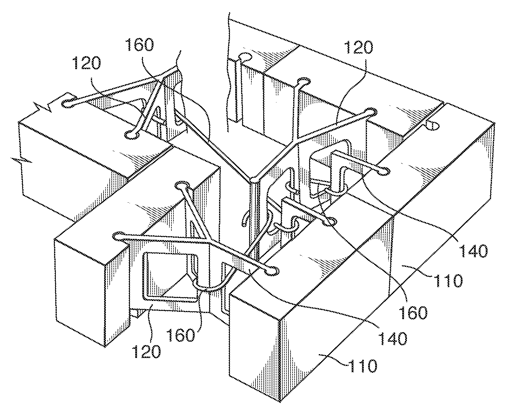
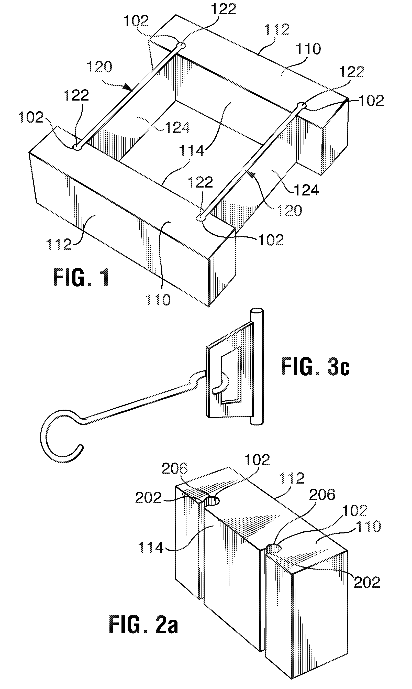
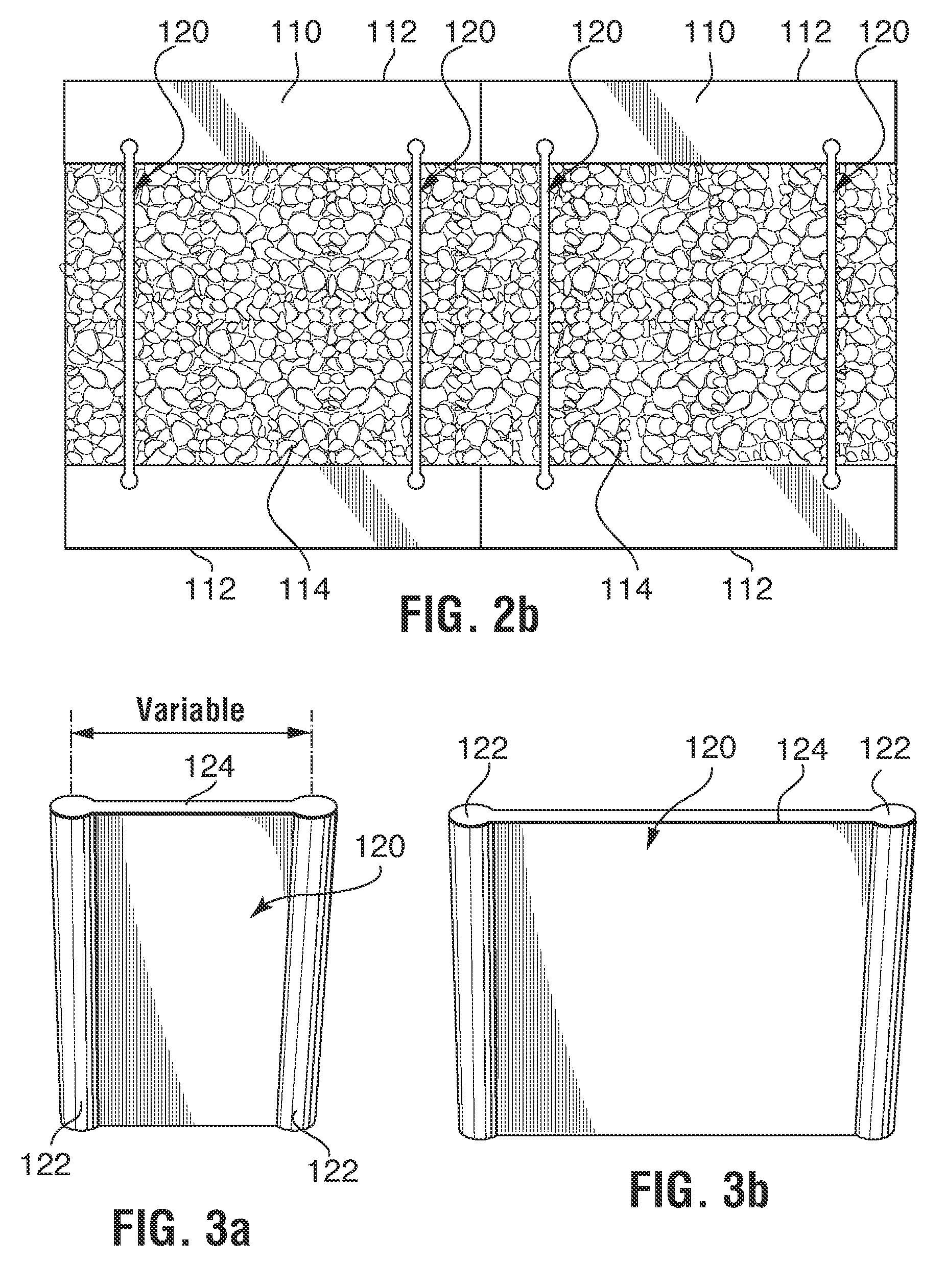
[0031]FIG. 1 illustrates the method in accordance with the invention of providing a decorative wall 100, such as a retaining wall or freestanding wall, by connecting pairs of facing panels 110 having a decorative surface 112 in a back-to-back arrangement. In the illustrated embodiment, each facing panel 110 is connected by way of connectors 120, with at least one other facing panel. The connectors respectively engage at least two facing panels. The preferred connectors 120, which are discussed in more detail with reference to FIGS. 3a-3c, 7 and 8 have at least a pair of spaced apart paralle...


PUM


Abstract

Disclosed is an economical and effective way of producing a double sided decorative wall using facing panels having a decorative face surface, in particular dry cast concrete panels having a regular surface structure, more preferably an embossed surface, most preferably a patterned surface. Further disclosed are wall components and a wall kit for a double sided decorative wall. The facing panels in the wall are stacked in a back-to-back arrangement into a pair of first and second back-to-back walls, which walls are interconnected by connectors which link at least one facing panel in the first wall to at least one facing panel in the second wall for forming the double sided decorative wall. The connecting members can be in individual connectors, or a combination of connectors for linking multiple facing panels or linking facing panels at corners or curves in the wall. The connectors can be of different length to enable the construction of decorative walls of different thickness. A modular wall system for double sided decorative walls forming both straight and curved walls is also disclosed. The system uses facing panels and connectors, wherein all facing panels are of equal thickness, but may have different lengths and may have different widths. The facing panels of the modular wall system all have graduated lengths, each length being a multiple of a base length L. Thus, the facing panels have lengths of 2L, 3L, 4L, 5L etc. To facilitate the formation of walls with corners, such as right angled corners, the facing panels preferably have a depth which is equal to L or a multiple of L. Building the decorative wall of two partial walls of facing panels with intermediate connectors renders the wall more economical than the previously known walls with base blocks and facing panels suspended from the base blocks on one or both sides.

Description

[0001]This application is a Continuation-in-Part Application from U.S. patent application Ser. No. 12 / 525,491, filed Jul. 31, 2009, which is a 371 of PCT / CA2004 / 000946, filed Dec. 21, 2007, which claims priority from U.S. Ser. No. 60 / 887,877, filed on Feb. 2, 2007, which are incorporated herein by reference in their entirety.FIELD OF THE INVENTION[0002]The present invention is generally directed toward decorative walls such as retaining walls and freestanding walls having a decorative surface. In particular, the invention is directed to modular walls with a decorative facing and components of such walls. More specifically, the present invention is directed toward walls, which have a pair of decorative surfaces.BACKGROUND OF THE INVENTION[0003]Retaining walls are used in landscaping around residential or commercial buildings. Retaining walls can be made of various materials, but for reasons of durability are most often either concrete structures cast in situ or walls formed of stacke...

Claims


Application Information

Patent Timeline
IPC IPC(8): E04B2/46E04B2/00E04C2/38
CPCE04B2/46E04B2/8641E04B2002/867E04B2002/0269E04B2002/0247E02D17/205E04B2/30E04B2/34E04B2002/0282E04B2103/02E04C1/00
Inventor AUBE, STEPHANECASTONGUAY, BERTINDAOUST, ROBERTTHOMASSEN, MARCEL
Owner LES MATERIAUX DE CONSTR OLDCASTLE CANADA
Why Eureka
Try Eureka