Railway vehicle drive unit
a technology for driving units and railways, which is applied in the direction of locomotive transmissions, gearing, electric motor propulsion transmissions, etc., can solve the problems of reducing the torque loss of the reducer, affecting the lubrication performance of the reducer, and the lubricant oil amount is likely to run short in the vicinity of the input shaft, so as to achieve superior lubrication performan
- Summary
- Abstract
- Description
- Claims
- Application Information
AI Technical Summary
Benefits of technology
Problems solved by technology
Method used
Image
Examples
first embodiment
(1) First Embodiment
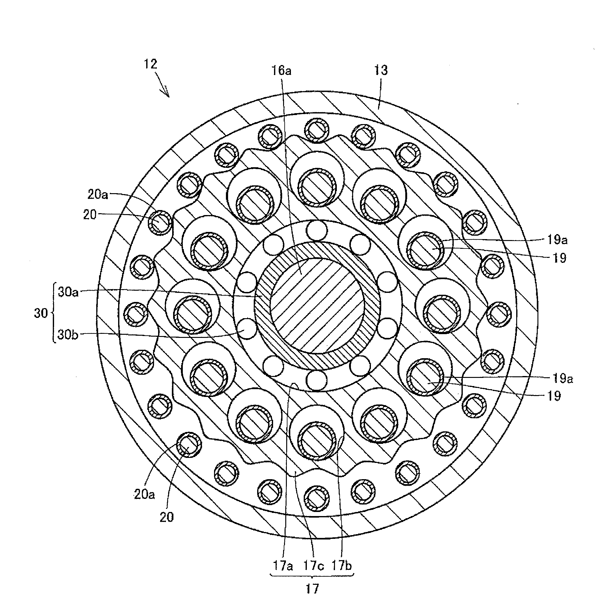
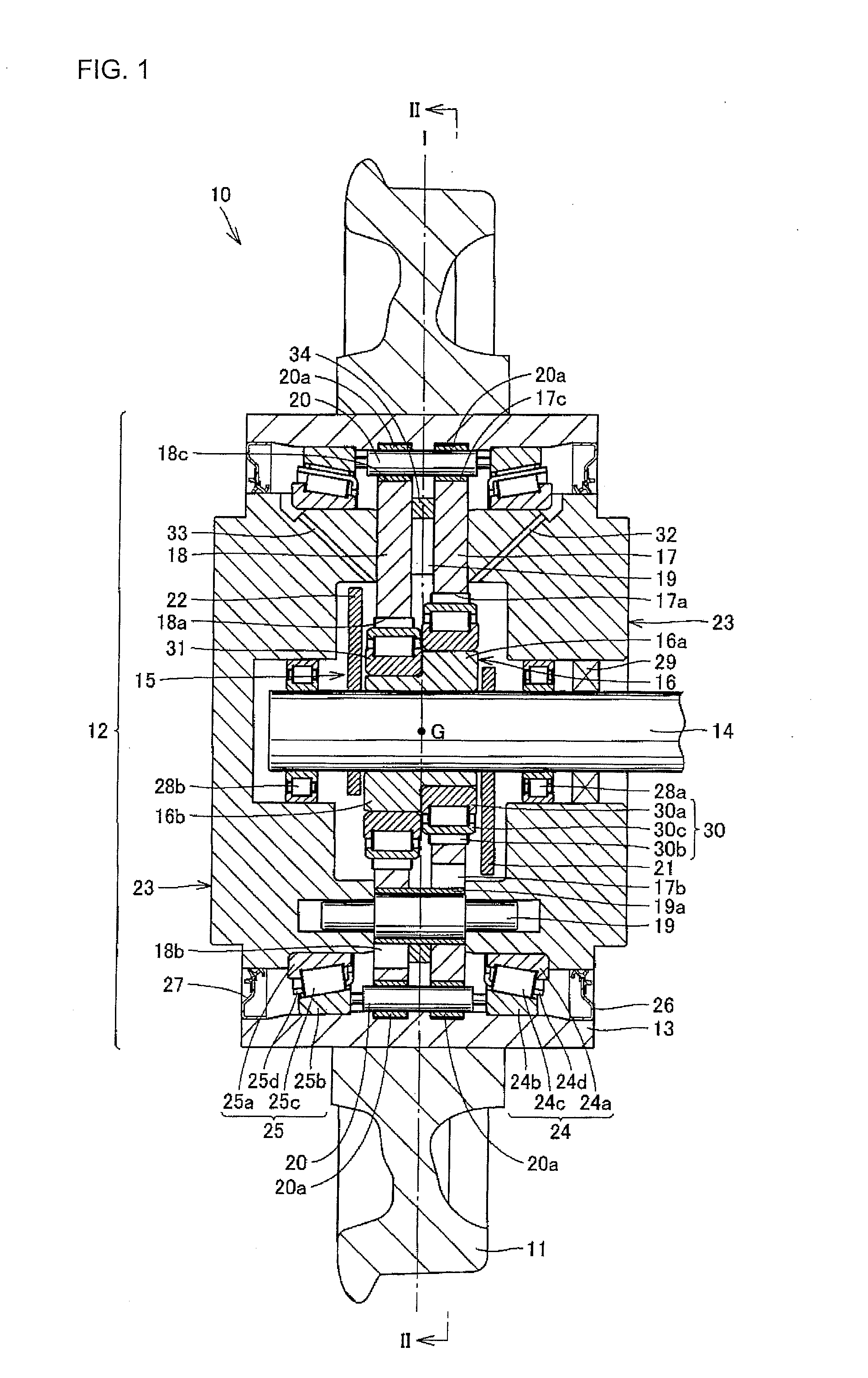
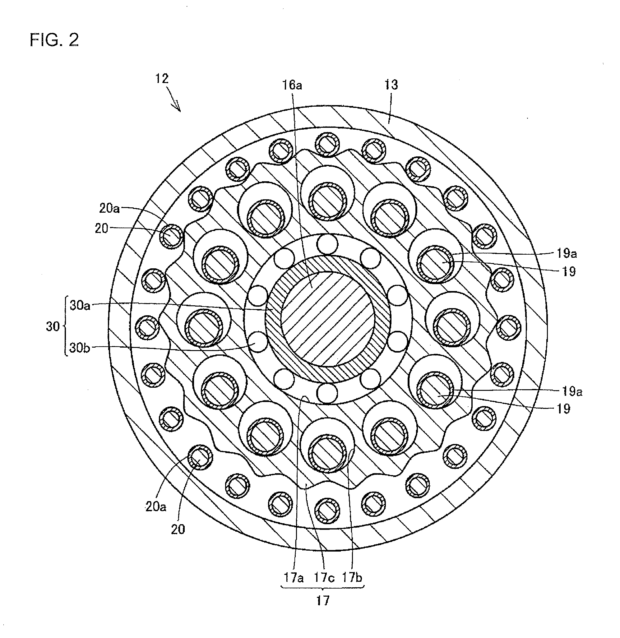
[0062]A description will be made of a railway vehicle drive unit 12 according to one embodiment of the present invention and a railway vehicle wheel drive device 10 including the railway vehicle drive unit 12, with reference to FIGS. 1 to 3. In addition, FIG. 1 is a schematic cross-sectional view of the railway vehicle wheel drive device 10, FIG. 2 is a cross-sectional view taken along a line II-II in FIG. 1, and FIG. 3 is an enlarged view showing a periphery of eccentric parts 16a and 16b.
[0063]First, referring to FIG. 1, the railway vehicle wheel drive device 10 is composed of a railway vehicle wheel 11 (hereinafter, referred to as “the wheel 11”) and the drive unit 12 (hereinafter, referred to as “the railway vehicle drive unit 12”) held on an inner diameter surface of the wheel 11 to reduce rotation speed of a drive source (not shown) and transmit it to the wheel 11, and arranged in a lower part of a railway vehicle body (not shown).
[0064]The railway vehicle...
second embodiment
(2) Second Embodiment
[0103]Next, a second embodiment of the present invention will be described. FIG. 4 is a view showing a configuration of a railway vehicle wheel drive device according to the second embodiment. Referring to FIG. 4, according to this embodiment, a railway vehicle drive unit 12 is composed of a reducer housing 13, an input side rotation member 14, a reducing mechanism 15, a carrier 23 as a fixed member, and first and second axle bearings 24 and 25, which is the same as the above embodiment.
[0104]However, this embodiment is different from the above embodiment in that a lubricant oil holding chamber 35 is provided in the carrier 23. Therefore, a part different from that of the above embodiment will be described in detail, and the same part has the same reference, and its description is not reiterated.
[0105]The reducer housing 13 has a space sealed with a lubricant oil, and is held on an inner diameter surface of a wheel 11. The space sealed with the lubricant oil mea...
third embodiment
(3) Third Embodiment
[0119]Next, a third embodiment of the present invention will be described. FIGS. 6 to 14 are views showing a railway vehicle drive unit according to the third embodiment. Referring to these drawings, a description will be made of a railway vehicle drive unit 112 according to the third embodiment and a railway vehicle wheel drive device 110 including the railway vehicle drive unit 112. In addition, FIG. 6 is a schematic cross-sectional view of the railway vehicle wheel drive device 110, FIG. 7 is a cross-sectional view taken along a line VII-VII in FIG. 6, FIG. 8 is an enlarged view of a periphery of ecentric members 116a and 116b, FIG. 9 is an enlarged view of an inner pin 119, FIG. 10 is an enlarged view of an inner pin 120, FIGS. 11 to 13 are views showing pumps as a lubricant oil transferring mechanism, and FIG. 14 is a view showing a counterweight 122 provided with a lubricant oil transferring mechanism.
[0120]First, referring to FIG. 6, the railway vehicle wh...
PUM
 Abstract
Description
Claims
Application Information
 - R&D
- Intellectual Property
- Life Sciences
- Materials
- Tech Scout
- Unparalleled Data Quality
- Higher Quality Content
- 60% Fewer Hallucinations
Browse by: Latest US Patents, China's latest patents, Technical Efficacy Thesaurus, Application Domain, Technology Topic, Popular Technical Reports.
© 2025 PatSnap. All rights reserved.Legal|Privacy policy|Modern Slavery Act Transparency Statement|Sitemap|About US| Contact US: help@patsnap.com


