Connection member and separation membrane module using the same

a technology of separation membrane and connection member, which is applied in the direction of membranes, separation processes, multi-stage water/sewage treatment, etc., can solve the problems of cumbersome work of connecting the membrane elements, water quality may be degraded, and complex structure, so as to prevent leakage from a supply side to a permeation side, reduce frictional resistance at the time of installation, and improve the effect of separation membrane elements

Inactive Publication Date: 2011-01-06
NITTO DENKO CORP
View PDF11 Cites 7 Cited by
  • Summary
  • Abstract
  • Description
  • Claims
  • Application Information

AI Technical Summary

Benefits of technology

[0023]In the separation membrane module of the present invention, the above-described connection member of the present invention is used, so that leakage from a supply side to a permeation side can be prevented by a simple means in the same manner as described above, and moreover, the handling property at the time of installing the separation membrane elements into the pressure-resistant vessel can be improved.
[0024]With respect to the above, it is preferable that the connection member is the connection member having two or more protrusions, and each of the protrusions abuts against the inner surface of the pressure-resistant vessel when the plurality of connected separation membrane elements are installed into the pressure-resistant vessel. With this constitution, the frictional resistance at the time of installation can be reduced as described above, so that the separation membrane elements can be easily installed into the pressure-resistant vessel. Moreover, connection between the pressure-resistant vessel and the connector connected to the central pipe of the separation membrane element located at the most downstream side is facilitated.
[0025]With respect to the above, it is preferable that the end surface holding members are also disposed respectively in the upstream-side end of the separation membrane element located at the most upstream side and in the downstream-si...

Problems solved by technology

This generates abrasion of the O-ring 35, whereby leakage occurs from the supply side to the permeation side, raising a fear that the water quality may be degraded.
However, none of the...

Method used


Image

  • Connection member and separation membrane module using the same
  • Connection member and separation membrane module using the same
  • Connection member and separation membrane module using the same

Examples


Embodiment Construction

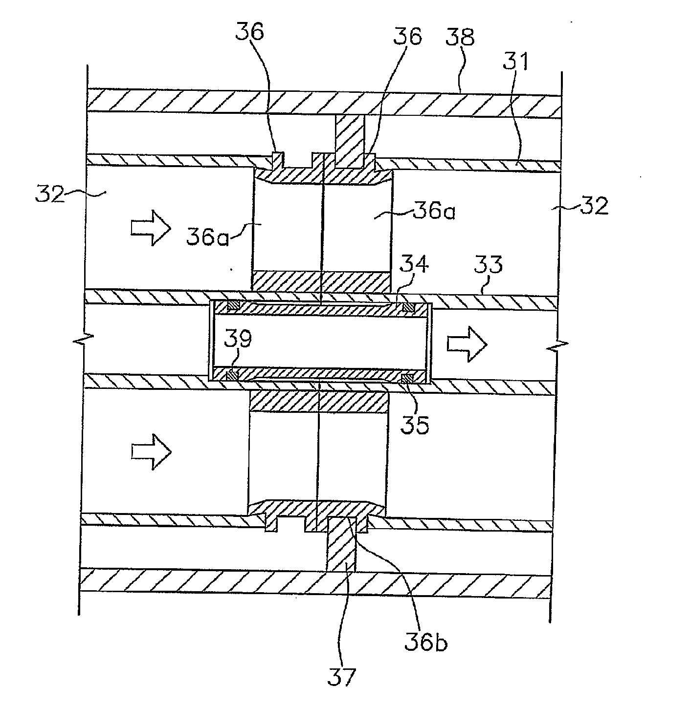
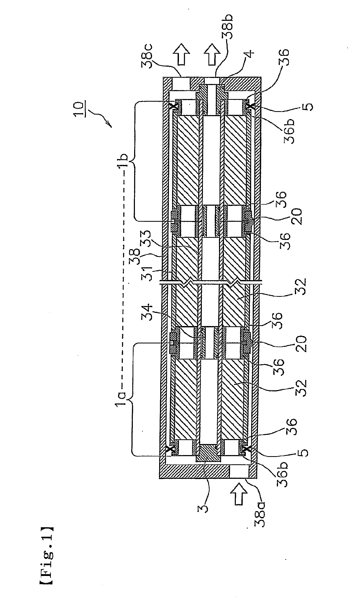
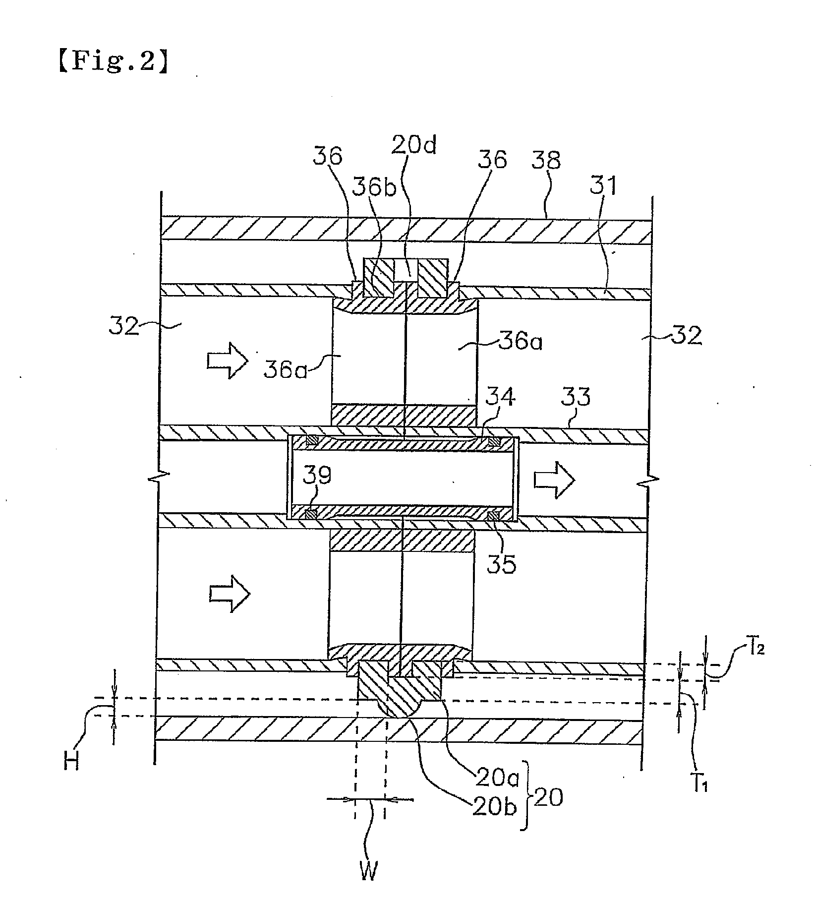
[0055]Hereafter, embodiments of the present invention will be described with reference to the drawings. FIG. 1 is a schematic cross-sectional view of a spiral-type membrane module which is one example of the separation membrane module of the present invention, and FIG. 2 is a cross-sectional view of an essential part illustrating the element connection part of the spiral-type membrane module of FIG. 1. Also, FIGS. 3 and 4 are schematic plan views illustrating one example of the connection member of the present invention. Here, some parts are illustrated in a larger scale or in a smaller scale for the sake of simplification of the description. Also, the members having the same constitution as those described in the background art will be denoted with the same symbols, and the description thereof will be omitted.

[0056]Referring to FIG. 1, in a spiral-type membrane module 10, a plurality of membrane elements are connected in series and installed into a pressure-resistant vessel 38 from...


PUM

PropertyMeasurementUnit
Electrical resistanceaaaaaaaaaa

Abstract

Provided are a connection member capable of preventing leakage from a supply side to a permeating side from occurring by a simple means; and a separation membrane module using the connection member. The connection member (20) is used to connect in series a plurality of separation membrane elements equipped with end surface holding members (36) and to install the separation membrane elements in a pressure-resistant vessel (38). The connection member (20) is characterized in that, when the separation membrane elements are connected to each other, the connection member is engaged with respective grooves (36b) of the end surface holding members (36) adjacent to each other.

Description

TECHNICAL FIELD[0001]The present invention relates to a connection member used to connect in series a plurality of separation membrane elements equipped with end surface holding members and to install the separation membrane elements into a pressure-resistant vessel, as well as to a separation membrane module using the same.BACKGROUND ART[0002]Separation membrane modules can be classified into a spiral type, a plain membrane type, a hollow thread type, and others depending on the mode of a separation membrane unit, where, by permeating liquid or gas, components can be separated or concentrated. For example, a spiral-type membrane module generally has a structure such that a plurality of spiral-type membrane elements (hereafter also referred to as “membrane elements”) having a tubular shape are connected in series and installed into a pressure-resistant vessel (for example, see the patent document 1). This membrane element typically has a wound body of separation membrane units (here...

Claims


Application Information

Patent Timeline
IPC IPC(8): B01D69/00F16L17/00
CPCB01D63/106B01D2319/022B01D63/12
Inventor UDA, YASUHIROHAMADA, TOSHIMITSUBEPPU, MASASHICHIKURA, SHINICHITAHARA, NOBUHARUTAKATA, MASAKATSU
Owner NITTO DENKO CORP
Why Eureka
Try Eureka