Shower Head

a shower head and shower head technology, applied in the field of shower head, can solve the problems of reducing spraying efficiency, reducing spraying efficiency, and reducing the spraying efficiency of the lower dis

Inactive Publication Date: 2011-01-06
GLOBE UNION INDAL
View PDF7 Cites 68 Cited by
  • Summary
  • Abstract
  • Description
  • Claims
  • Application Information

AI Technical Summary

Benefits of technology

The primary object of the present invention is to provide a shower head whic

Problems solved by technology

The water is not limited in the hollow flowing space but flowing freely to lose its flowing energy and pressure, thereby lowering spraying efficiency.
In addition, a conventional shower head with a larger size includes a hollow flowing space, therefore its lower disc bears more pressure to deform the shower head to generate a water leak.
Furthermore, the watering passage includes a number of sector areas, b

Method used


Image

  • Shower Head
  • Shower Head
  • Shower Head

Examples


Embodiment Construction

The present invention will be clearer from the following description when viewed together with the accompanying drawings, which show, for purpose of illustrations only, the preferred embodiment in accordance with the present invention.

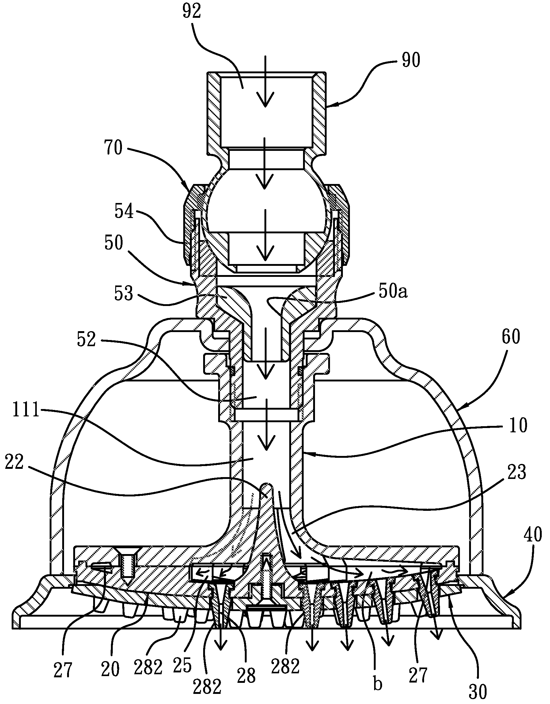
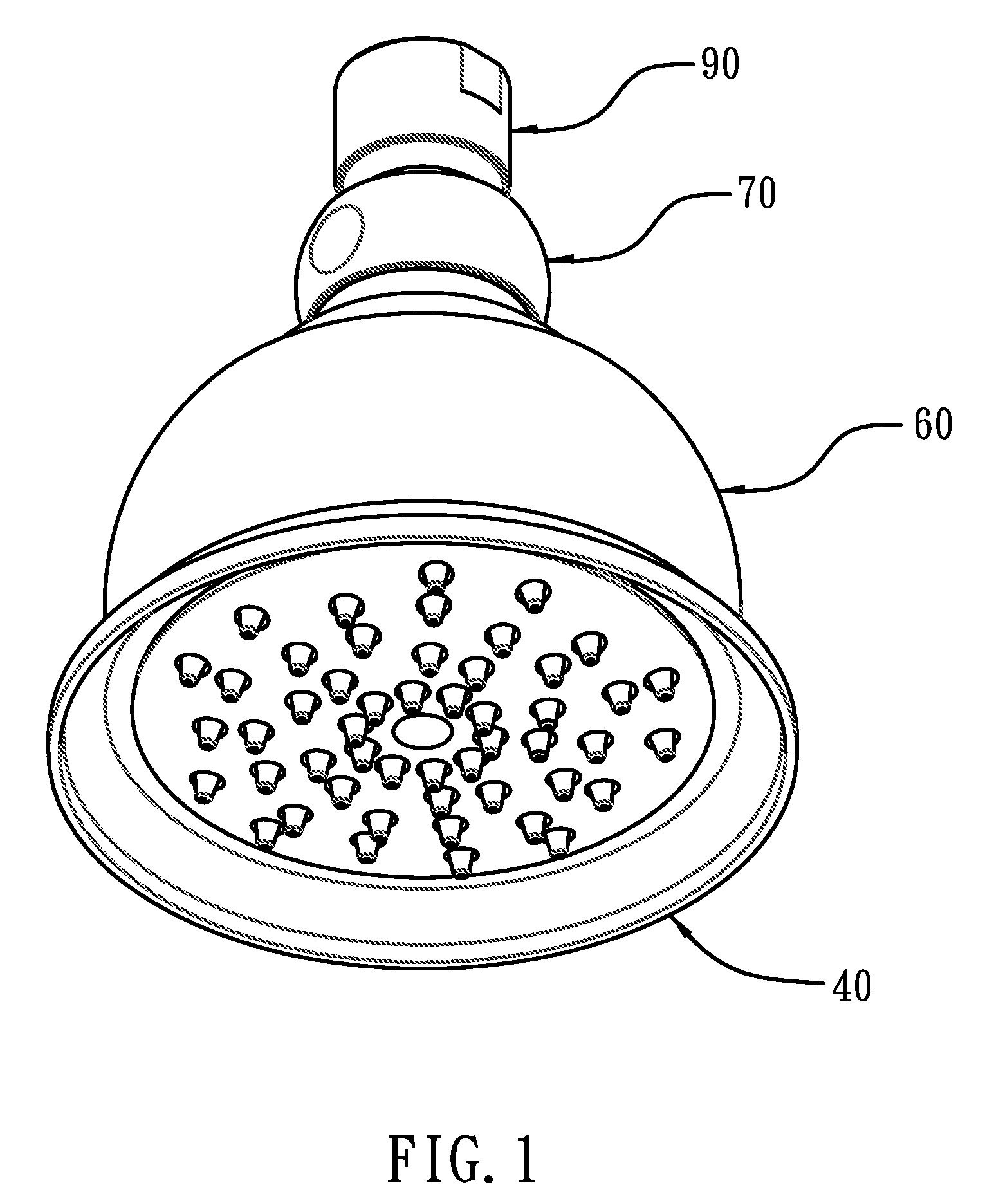
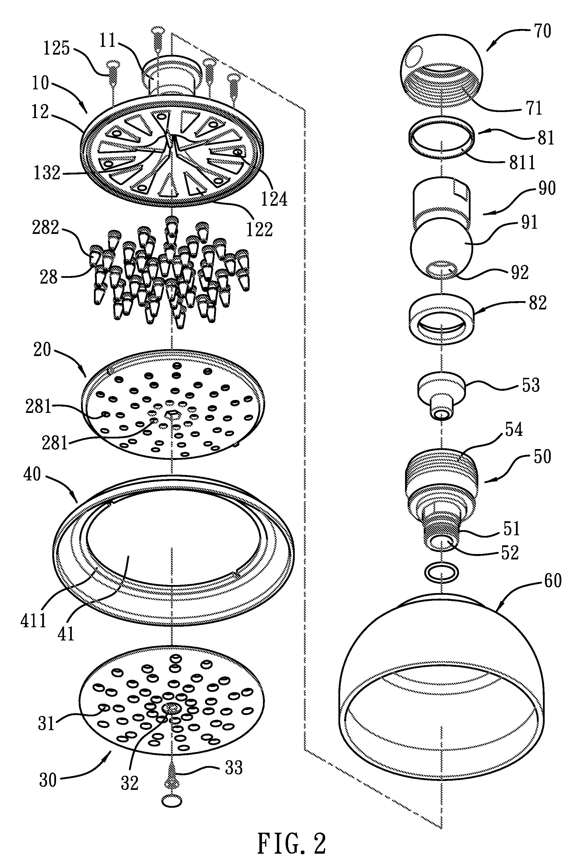
Referring to FIGS. 1-4, a shower head according to a preferred embodiment of the present invention comprises an upper body 10, a lower body 20, an annular lid 30, a lower cover 40, a coupling member 50, an upper cover 60, a casing 70, an upper washer 81, a lower washer 82, and a spherical connector 90.

The upper body 10, as shown in FIGS. 5-9, includes a tubular portion 11, a disc portion 12, a connection 13 between the tubular portion 11 and the disc portion 12, wherein the tubular portion 11 includes a passage 111 formed therein and having first inner threads 112 arranged on a top end of the passage 111, the connection 13 includes an arcuately-curved wall 131 extending radially from a lower side of the passage 111 and having a plurality of impellers 1...


PUM


Abstract

A shower head comprises an upper body including a tubular portion having a passage formed therein, a connection including an arcuately-curved wall extending radially and having multiple spaced impellers extending downward, each impeller including an arc-shaped biasing end mounted on an inner side thereof and extending downward to define a fixing space, a disc portion including an upper surface fixed on a bottom end thereof; a lower body including a concave lower wall having a conical guiding member extending upward and having an arcuate peripheral side extending downward, wherein the peripheral side is received in the fixing space to abut against the biasing ends so that the peripheral side defines an arc-shaped offset passage extending downward between the arcuately-curved wall and any two abutting impellers; the lower wall engaging with the upper body to define multiple radially extending channels and including multiple outlets to spray water arranged along the channels.

Description

BACKGROUND OF THE INVENTION1. Field of the InventionThe present invention relates to a shower head which supplies water with small flowing amount and high efficiency.2. Description of the Prior ArtConventional shower head includes an upper disc with an inlet and a lower disc connected to a lower side of the upper disc and having a plurality of outlets, a hollow flowing space between the upper and the lower discs, such that after water flows into the flowing space from the inlet of the upper disc, the water will spray outward from the outlets. However, such a conventional shower head has the following disadvantages:The water is not limited in the hollow flowing space but flowing freely to lose its flowing energy and pressure, thereby lowering spraying efficiency. Besides, the watering amounts of the outlets are not equal as the watering amount is less than 2.5 GPM, and the shower head does not face downward but being limited at a predetermined angle to reduce flowing energy more grea...

Claims


Application Information

Patent Timeline
IPC IPC(8): B05B1/18
CPCB05B1/34B05B1/18B05B1/3402
Inventor CHANG, CHUNG-HSIANG
Owner GLOBE UNION INDAL
Why Eureka
Try Eureka