
Adaptive Load Limiting Seat Belt Retractor

a seat belt and load limit technology, which is applied in the direction of belt retractors, vehicle safety belts, vehicle components, etc., can solve the problems of limited payout, restraining force may actually dip below the predetermined level, and seat belt may impose very severe loads on the user

Inactive Publication Date: 2011-01-06
AUTOLIV DEV AB
View PDF11 Cites 9 Cited by
  • Summary
  • Abstract
  • Description
  • Claims
  • Application Information

AI Technical Summary

Benefits of technology

[0009]Preferably the torsion elements are elements adapted to twist, allowing limited rotation of the spool relative to the head member and thus limited paying out of the seat belt, whilst undergoing plastic deformation, in order to limit the seat belt load.

Problems solved by technology

However, in such a crash situation, particularly in a high speed impact, the seat belt may impose very severe loads on the user in the course of the impact.
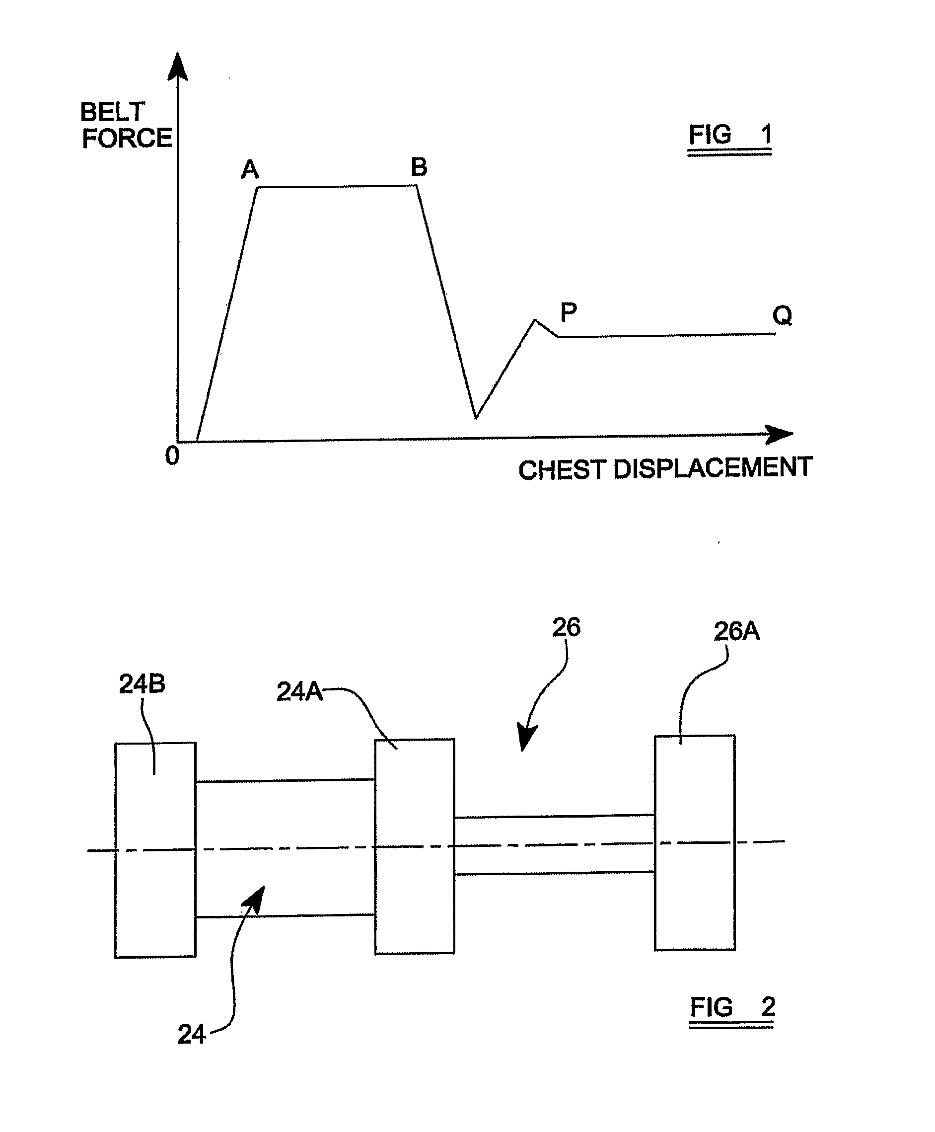
The applicants have found that in a two-stage load limiting mechanism of the above kind, a problem arises in that, in the period of the change over of the load limiter from the higher restraining force to the lower restraining force the restraining force may actually dip below the level predetermined as the lower restraining force.
Preferably the torsion elements are elements adapted to twist, allowing limited rotation of the spool relative to the head member and thus limited paying out of the seat belt, whilst undergoing plastic deformation, in order to limit the seat belt load.

Method used


Image

  • Adaptive Load Limiting Seat Belt Retractor
  • Adaptive Load Limiting Seat Belt Retractor
  • Adaptive Load Limiting Seat Belt Retractor

Examples


Embodiment Construction

[0021]A vehicle safety belt arrangement incorporating a load limiter as described below is intended to operate as follows in a crash situation in which the vehicle concerned encounters a frontal impact with another vehicle or with some other object. Where the impact occurs at high speed, such that an absolutely fixed seat belt would place excessively high loads on an occupant wearing the seat belt, the load limiter initially allows limited rotation of the seat belt retractor spool in response to a seat belt tension in excess of a predetermined high value, for a limited period. However, after such period, after the occupant has experienced some deceleration and when the associated vehicle airbag has begun to play its part in reducing the momentum of the occupant, the limiting tension in the seat belt should be reduced to a lower level.

[0022]Referring to FIG. 1, in a two-stage load limiter mechanism for a seat belt retractor, from the beginning of the vehicle impact, indicated at orig...


PUM


Abstract

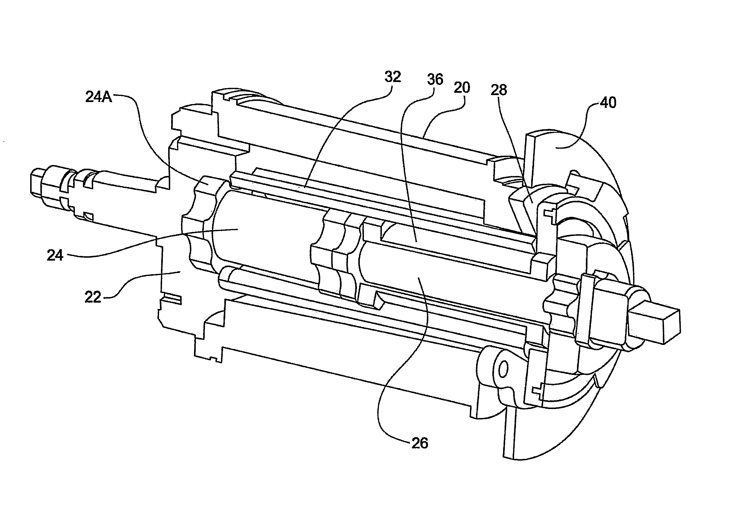
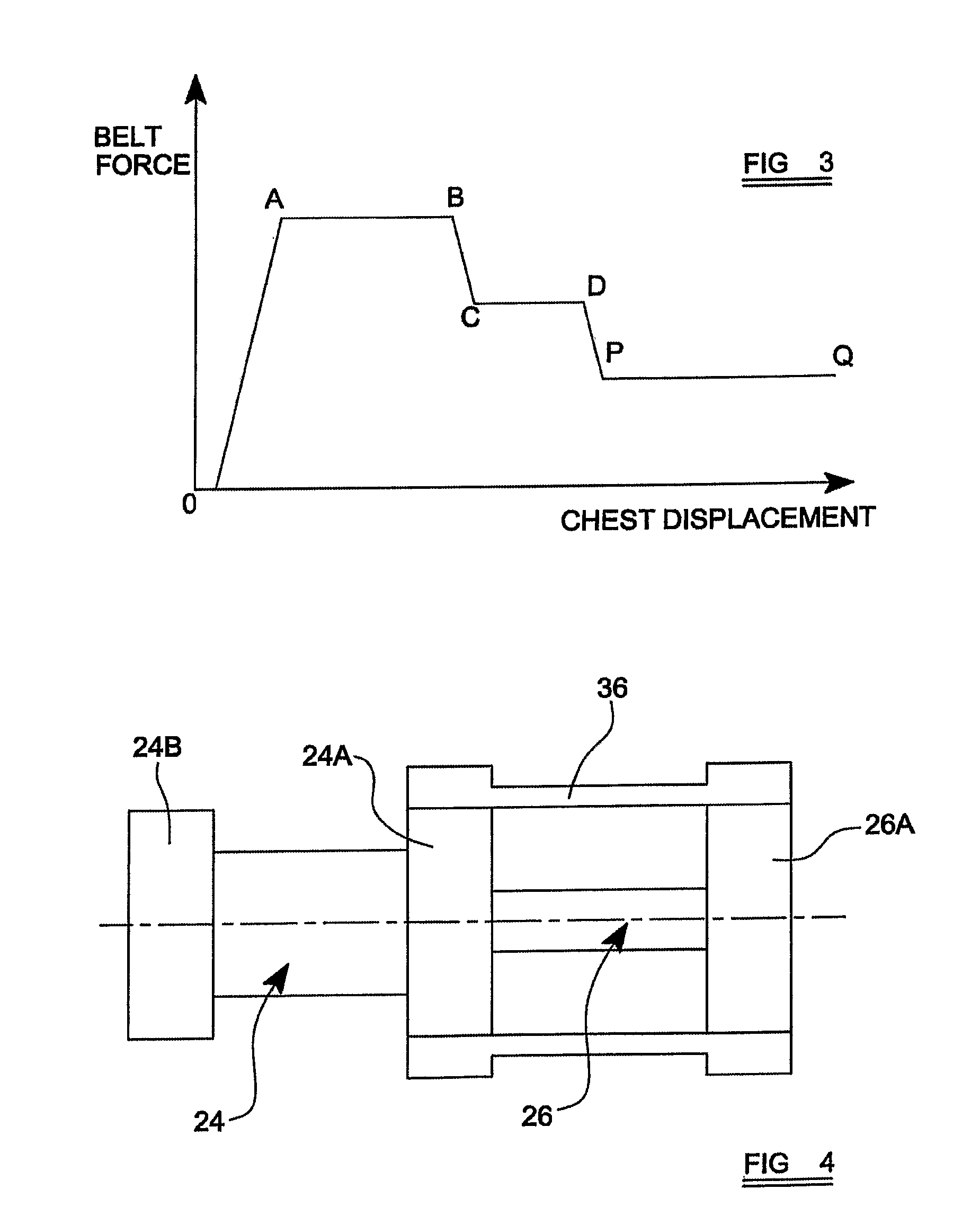
A safety seat belt arrangement comprises a retractor or spool assembly including a spool (20), carrying the seat belt, rotatable in a frame (18) unless blocked by a blocking mechanism (25), the spool assembly including a head member (22) cooperating with the blocking mechanism. A load limiting torsion bar assembly within the spool and acting between the head member and the spool includes a high level torsion bar portion (24), a low level torsion bar portion (26) and an intermediate torsion element in the form of a torsion pipe (36) fixed at its ends with respect to the ends of the torsion bar portion (26). A torque tube (32) initially provides a direct drive connection between the outer end of the spool (20) and the outer end (24A) of the high level torsion bar portion, so that, in a frontal impact situation, in which the blocking mechanism blocks rotation of the head member, the torque applied to the spool by the belt tension is transferred to the head member principally via the high level torsion bar (24), limiting the belt tension to a relatively high level, until the torque tube is disconnected from the outer end of the spool in a changeover operation effected by a changeover mechanism (28, 40, 42) after which the belt tension is limited by twisting of the bar portion (26) and the torsion pipe (36) together, until the torsion pipe breaks, leaving rotation of the spool restrained only by twisting of the low level torsion bar part (26).

Description

CROSS REFERENCE TO RELATED APPLICATION[0001]This application claims priority to PCT patent application PCT / SE2007 / 000884 filed Oct. 5, 2007.FIELD OF THE INVENTION[0002]This invention relates to a load limiting mechanism for a seat belt retractor in a motor vehicle.BACKGROUND OF THE INVENTION[0003]A seat belt retractor generally comprises a spindle or spool to which the seat belt is attached at one end and around which the seat belt is wound, the spindle having an associated retraction spring by means of which the spindle is rotated to take up slack in the seat belt and to retract the seat belt into a stored position when the seat belt is not in use. The seat belt can be drawn out from the reel at a relatively low rate to allow an occupant to fasten the seat belt about his person, but an associated blocking mechanism locks the spindle against such paying-out rotation in a crash situation. However, in such a crash situation, particularly in a high speed impact, the seat belt may impos...

Claims


Application Information

Patent Timeline
Patent Type & Authority Applications(United States)
IPC IPC(8): B60R22/36B60R22/34
CPCB60R22/3413B60R2022/289B60R2022/287
Inventor WIGSTROM, FREDRIKGOTSTEN, HENRIKFRIEDLANDER, HENRIK
Owner AUTOLIV DEV AB
Learn More