
Wireless Communication Apparatus

a communication apparatus and wireless technology, applied in the field of wireless communication apparatus, can solve the problems of deteriorating reproduction quality and inability to absorb jitter, and achieve the effect of prolonging the time to absorb difference, slowing down the reproduction speed of application, and improving the communication quality of the second wireless communication system

Inactive Publication Date: 2011-01-06
KYOCERA CORP
View PDF6 Cites 20 Cited by
  • Summary
  • Abstract
  • Description
  • Claims
  • Application Information

AI Technical Summary

Benefits of technology

[0067]In order to perform handover from the first wireless communication network to the second wireless communication network, the wireless communication apparatus according to the first aspect previously obtains the preparation time for handover and the delay time of each of the first wireless communication network and the second wireless communication network. Thereby, when the delay time of the second wireless communication network of a handover destination is longer than that of the first wireless communication network of a handover source, for example, it enables to know for how long and how long after determination to start preparation for handover the packet will not arrive. In addition, in order to reproduce packets received from the first wireless communication network of the handover source even in a period packets do not arrive, the reproduction speed can be controlled so as to absorb a difference in the delay time between the first wireless communication network and the second wireless communication network, taking a long time from determination to start preparation for handover. It is thus possible to reproduce the packets at a speed close to a standard reproduction speed by reducing a difference from the standard reproduction speed, which enables handover from the first wireless communication network to the second wireless communication network without deteriorating the reproduction quality and a real-time property.
[0068]In order to perform handover from the first wireless communication network to the second wireless communication network, the wireless communication apparatus according to the fifth aspect previously obtains the preparation time for handover, the delay time of each of the first wireless communication network and the second wireless communication network, and the data amount in the jitter buffer at the time of determination to start preparation for handover and, based on such information obtained, controls to slow down the reproduction speed of the application. Accordingly, it is possible to extend a time to absorb the difference in the delay time by slowing down the reproduction speed such that the data amount in the jitter buffer becomes zero at a time to start receiving data from the second wireless communication network of the handover destination, for example. It is thus possible to reproduce the packets at a speed much closer to the standard reproduction speed, which enables handover from the first wireless communication network to the second wireless communication network without deteriorating the reproduction quality and the real-time property.
[0069]In order to perform handover from the first wireless communication network to the second wireless communication network, the wireless communication apparatus according to the tenth aspect previously obtains the preparation time for handover, the delay time of each of the first wireless communication network and the second wireless communication network, the data amount in the jitter buffer at the time of determination to start preparation for handover, and the communication quality of the second wireless communication system of the handover destination. Based on, such information obtained, the wireless communication apparatus controls the reproduction speed of the application. Thereby, when the delay time of the second wireless communication network of the handover destination is longer than that of the first wireless communication network of the handover source and the communication quality of the second wireless communication system of the handover destination is not good, for example, it is possible to accumulate the data in the jitter buffer before performing handover in consideration of accumulation of the delay times of received data after handover. Accordingly, it is possible to reproduce the packets at a speed close to the standard reproduction speed while extending the time to absorb the difference in the delay times by slowing down the reproduction speed before and after handover, which enables handover from the first wireless communication network to the second wireless communication network without deteriorating the reproduction quality and the real-time property.

Problems solved by technology

Moreover, when there is no packet in the jitter buffer since the jitter is large, and therefore silence occurs, or when too many packets are received in a short period to be stored in the jitter buffer, the communication terminal changes a reproduction speed, discards received packets, or changes a size of the jitter buffer.
As a result, since there is no packet to reproduce at least during this period, it causes silence and deteriorates reproduction quality.
In such a case, moreover, since packets are reproduced immediately after being received from the wireless communication network B of the handover destination, it is not possible to absorb jitter.

Method used


Image

  • Wireless Communication Apparatus
  • Wireless Communication Apparatus
  • Wireless Communication Apparatus

Examples


first embodiment

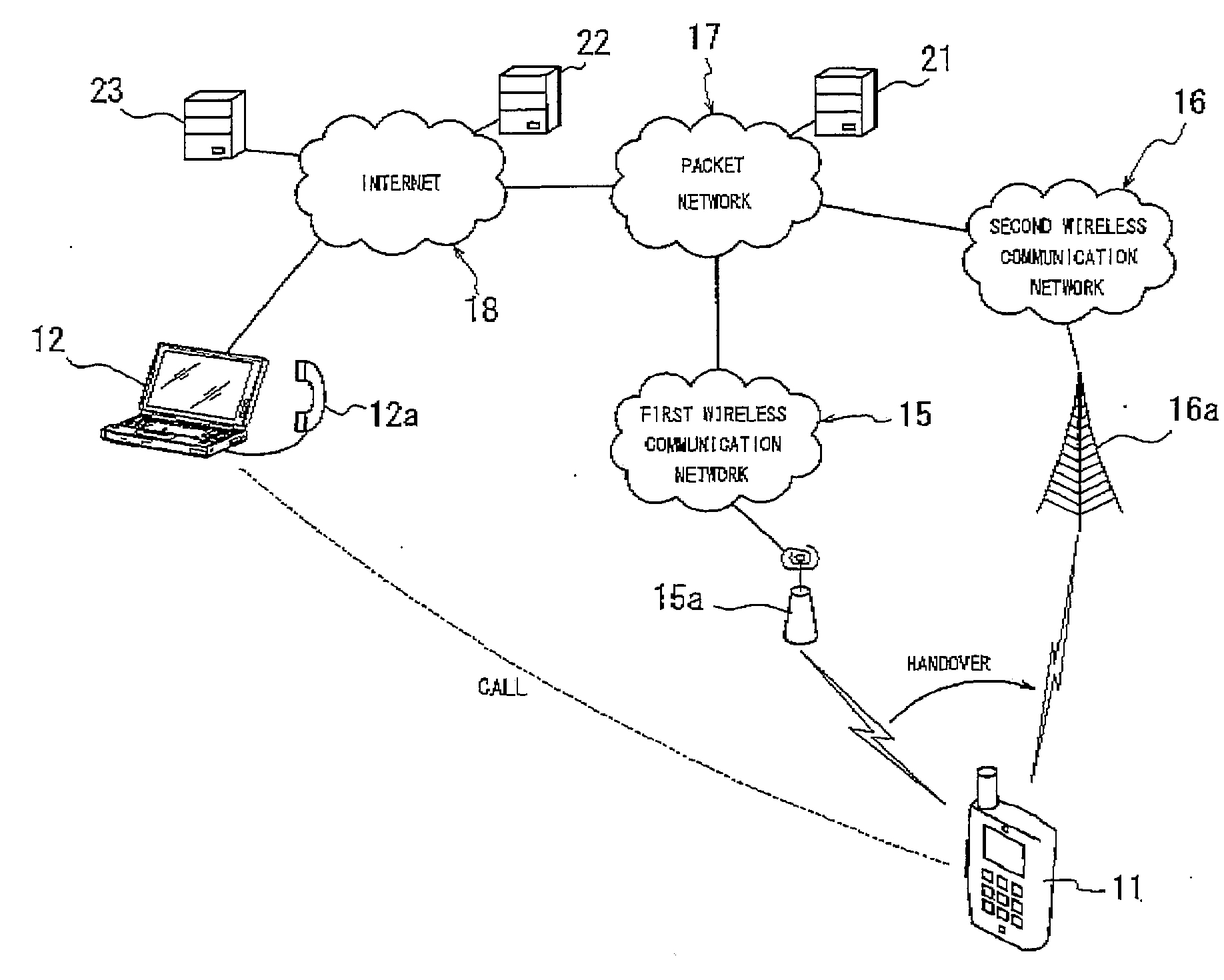
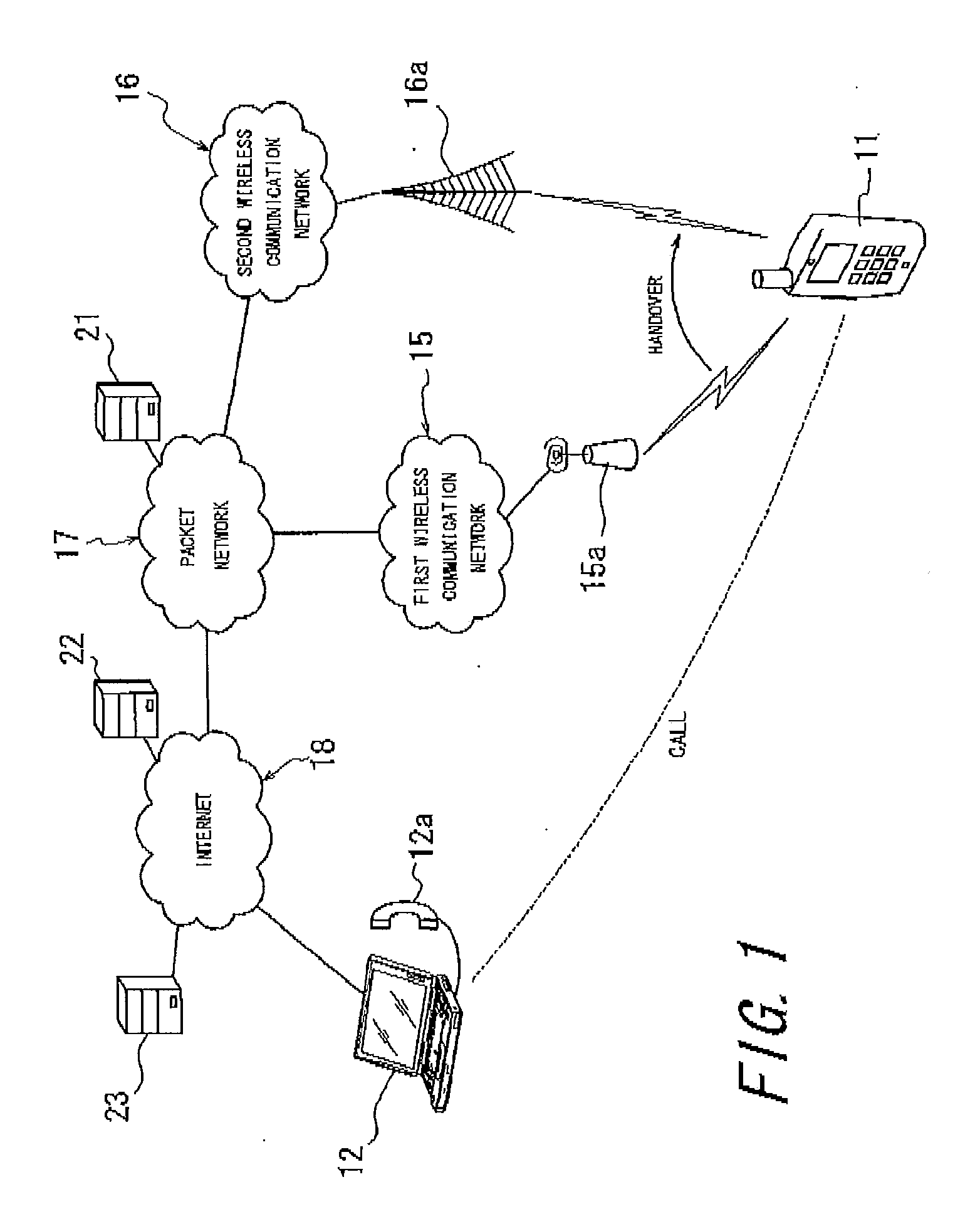
[0116]FIG. 1 is a diagram illustrating a schematic constitution of an example of a communication network which a wireless communication apparatus according to a first embodiment of the present invention can use. FIG. 1 shows a case where a wireless communication apparatus 11, which is a mobile node, calls a counterpart communication terminal 12, which is a correspondent node, using VoIP, an application for real-time communication. The wireless communication apparatus 11 can perform handover between a first wireless communication network 15 and a second wireless communication network 16. The first wireless communication network 15 and the second wireless communication network 16 are connected to the internet 18 via a packet network 17.

[0117]Here, the first wireless communication network 15 may be constituted of a wireless LAN, for example, whereas the second wireless communication network 16 may be constituted of a mobile phone network such as cdma 2000 EV-DO, for example. A delay ti...

second embodiment

[0182]According to a second embodiment of the present invention, a wireless communication apparatus 11 has the constitution as described in the first embodiment, and when the absolute delay time difference Ta (Ta=Tddn2−Tddn1) exceeds the predetermined value (>0) when handover is performed from the first wireless communication network 15 to the second wireless communication network 16, controls read-out of the received packets from the jitter buffer 47 such that the number of packets (data amount) in the jitter buffer 47 becomes zero at a time to start receiving the packets from the second wireless communication network 16 of the handover destination.

[0183]Accordingly, the reproduction speed calculation unit 56 of the telephone function unit 33 calculates the reproduction speed V of the received packets in the jitter buffer 47 from a formula 6 shown below based on the required handover information obtained from the handover information obtain unit 55 and the result of monitoring the ...

third embodiment

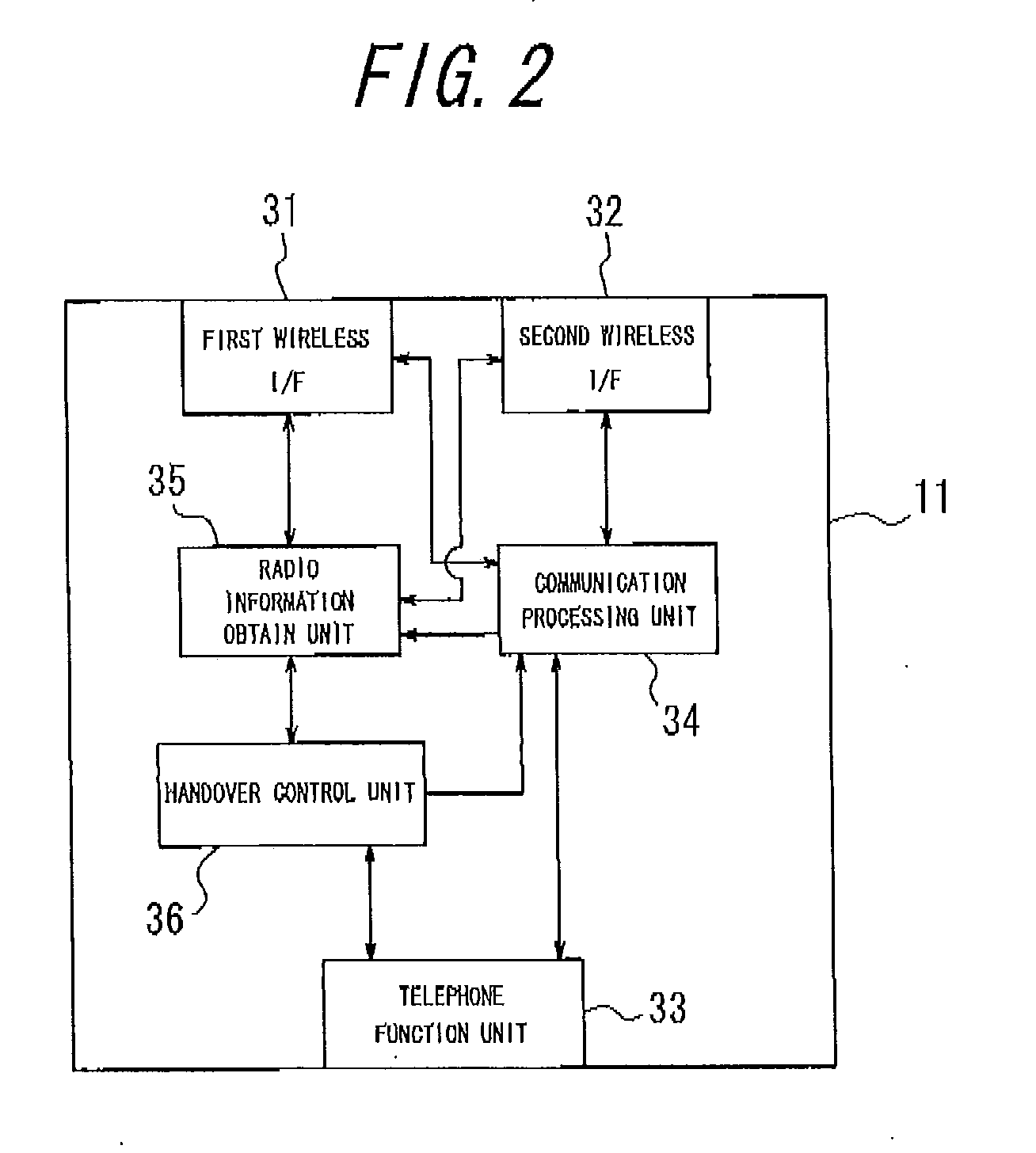
[0193]According to a third embodiment of the present invention, in the wireless communication apparatus 11 having the constitution as described in the first embodiment, the handover control unit 36 determines the handover schedule or cancels the handover schedule based on the communication quality obtained from the first wireless I / F 31 and the second wireless I / F 32. For example, when the communication quality obtained from the first wireless I / F 31 becomes equal or lower than the handover schedule determination threshold and, at that time, the communication quality obtained from the second wireless I / F 32 is equal to or higher than the communication quality obtained from the first wireless I / F 31 during the call forming a wireless link with the first wireless communication network 15, the handover control unit 36 determines the handover schedule to perform handover to the second wireless communication network 16 at the time the predetermined handover preparation time Tp passes, ba...


PUM


Abstract

In order to perform handover from a first wireless communication network 15 to a second wireless communication network 16, a preparation time for handover, communication quality after scheduled handover execution, and a delay time of each of the first wireless communication network and the second wireless communication network are obtained by a handover control unit 36 in advance. Based on such information obtained and data amount in a jitter buffer 47 at a time of determination to start preparation for handover, a reproduction speed of an application being executed is controlled. Thereby, it is possible to perform handover to a different wireless communication network without deteriorating the reproduction quality and real-time property.

Description

CROSS REFERENCE TO RELATED APPLICATION[0001]This application claims priority to and the benefit of Japanese Patent Application No. 2007-337123 filed on Dec. 27, 2007, and Japanese Patent Application No. 2008-19638 and Japanese Patent Application No. 2008-19642 both filed on Jan. 30, 2008, the entire contents of which are incorporated herein by reference.TECHNICAL FIELD[0002]The present invention relates to wireless communication apparatus capable of performing handover between different wireless communication networks.BACKGROUND ART[0003]In recent years, IETF (Internet Engineering Task Force) has been considering an IP mobility scheme for seamless movement capable of performing handover between a plurality of different wireless communication networks, such as a cellular phone network, a wireless LAN and the likes, so as to achieve ubiquitous environment. As a specific protocol of the IP mobility scheme, there are Mobile IPv4 and Mobile IPv6 (which are abbreviated as Mobile IP, herei...

Claims


Application Information

Patent Timeline
IPC IPC(8): H04W36/00H04W36/30
CPCH04W36/0016H04W36/02H04L65/80H04L65/1083H04W36/14H04W36/144H04W36/302H04W36/1446H04W36/0022H04W36/0033H04W36/22
Inventor NAGASAWA, CHIZUKOMORITA, KUGO
Owner KYOCERA CORP
Learn More