Sliding anchor

a technology of sliding bolts and bolts, applied in the direction of screwing, load-modifying fasteners, threaded fasteners, etc., can solve the problems of gradual use-up of sliding paths in dependence on rock movements, lengthening of sliding bolts, and inability to detect from the outside, so as to achieve rapid and reliable detection.

Inactive Publication Date: 2011-01-06
ATLAS COPCO SECOROC AB
View PDF38 Cites 3 Cited by
  • Summary
  • Abstract
  • Description
  • Claims
  • Application Information

AI Technical Summary

Benefits of technology

The invention aims at the provision of a sliding bolt that offers improved design conditions for the installation of a device that indicates in a rapidly and reliably detectable manner a sliding path that is still available.

Problems solved by technology

However, such a lengthening of the sliding bolt, i.e. the gradual using-up of the available sliding path in dependence upon the rock movements, is not readily detectable from the outside.

Method used


Image

  • Sliding anchor
  • Sliding anchor
  • Sliding anchor

Examples


second embodiment

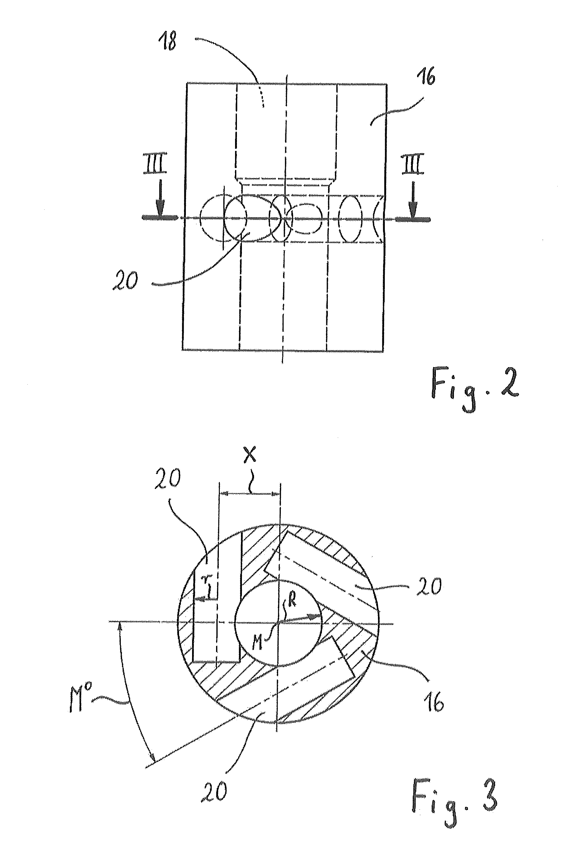
FIGS. 4 to 6 show a sliding body cage 16′, the basic construction of which corresponds to the sliding body cage 16. Unlike the sliding body cage 16, however, the sliding body cage 16′ has two planes disposed one above the other and having three recesses 20 each, wherein the recesses 20 of the one cross-sectional plane are offset in circumferential direction relative to the recesses 20 of the other cross-sectional plane such that all six recesses 20 together are distributed uniformly around the circumference of the sliding body cage 16′.

Each recess 20 is provided for receiving an, in the present case circular-cylindrical, sliding body 22, the outside diameter of which apart from conventional tolerances corresponds to the diameter of the recess 20, i.e. which completely fills the cross section of the recess 20. FIGS. 7 and 8 show the views, which correspond to FIGS. 5 and 6 and in which a sliding body 22 designed in the manner described above is disposed in each recess 20. As is clear...

first embodiment

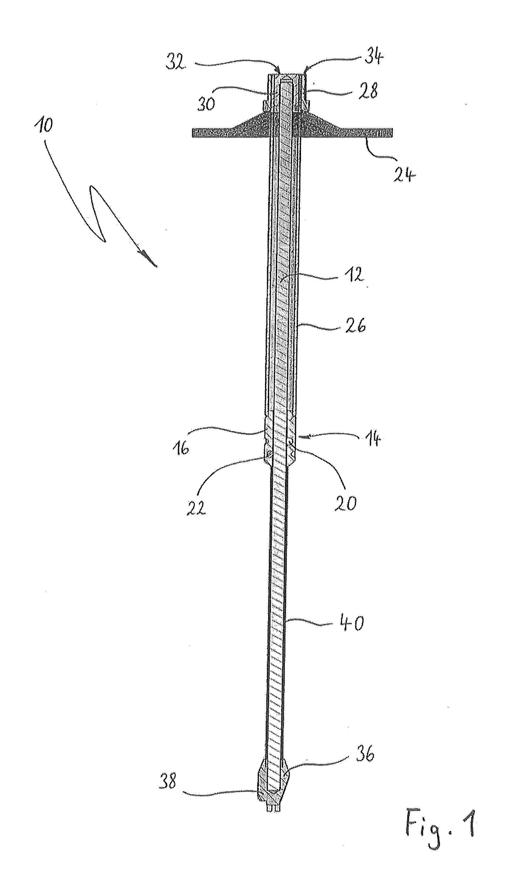
In the sliding bolt 10 illustrated in FIG. 1, the maximum length by which the sliding bolt 10 may yield, referred to as the sliding path, is defined by the axial distance between the stop element 30 and the sliding body cage 16 or 16′. If the sliding bolt of FIG. 1 yields because of increased load, then the sliding body cage 16 or 16′ slips in the direction of the stop element 30. When the sliding body cage 16 or 16′ strikes the stop element 30, a further lengthening of the sliding bolt 10 is no longer possible. During the sliding operation the stop element 30 moves from its initial position flush with the assembly adapter 28 further and further into the first protective tube 26, this making it possible to tell at a glance how far the sliding bolt has already yielded.

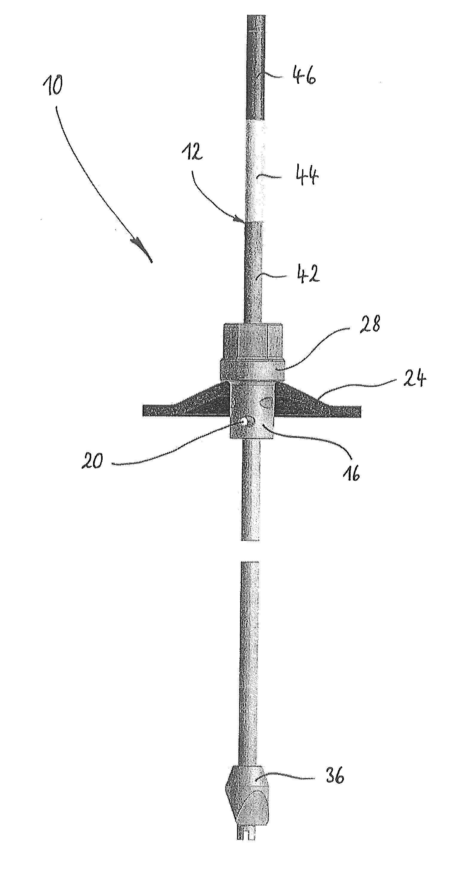
In the second embodiment of the sliding bolt 10 represented in FIG. 9 it is even easier to “read” the sliding path that is already used up because, as the bolt 10 slides, the colour-marked regions 42, 44 and 46 disappea...


PUM


Abstract

The invention relates to a sliding bolt (10) for introducing into a bore, having an anchor rod (12), on which is disposed a sliding control element (14) with a through-opening (18), through which the anchor rod (12) extends, wherein the sliding control element (14) comprises a sliding body cage (16) having at least one recess (20) for receiving a sliding body (22) that is in contact with the lateral surface of the anchor rod (12), and having an anchor plate (24), which is intended to lie against a region surrounding the mouth of the bore once the sliding bolt (10) has been introduced into the bore. In contrast to conventional sliding bolts, the anchor plate (24) is in load-transferring connection with the sliding body cage (16), with the result that it is easily possible to provide a device that indicates a sliding path of the sliding bolt that is still available.

Description

FIELD OF THE TECHNOLOGYThe invention relates to a sliding bolt for introducing into a bore, wherein the sliding bolt comprises an anchor rod, on which is disposed a sliding control element with a through-opening, through which the anchor rod extends, as well as an anchor plate, which is intended to lie against the region surrounding the mouth of the bore after the sliding bolt has been introduced into the bore, and wherein the sliding control element comprises a sliding body cage having at least one recess for receiving a sliding body that is in contact with the lateral surface of the anchor rod. Such a sliding bolt is known from WO 2006 / 034208 A1.BACKGROUNDSliding bolts belong to the group of so-called rock bolts. Rock bolts are used in mining, tunnel construction and special civil engineering to stabilize the wall of a gallery, tunnel or embankment. For this purpose, a bore that is conventionally between two and twelve metres long is driven from the gallery or tunnel into the rock...

Claims


Application Information

Patent Timeline
Patent Type & Authority Applications(United States)
IPC IPC(8): E21D21/00
CPCE21D21/008E21D21/0033
Inventor MEIDL, MICHAELCHARETTE, FRANCOIS
Owner ATLAS COPCO SECOROC AB
Why Eureka
Try Eureka