
Blower for dental use

a technology for dental use and blower, which is applied in the field of blowers for dental use, can solve the problems of slow operation of drying canals, discomfort for patients, and limited drying efficiency of paper cones, and achieve the effect of effectively drying endodontic canals in teeth, convenient use and rapid drying

Inactive Publication Date: 2011-01-06
SHIBRUN
View PDF15 Cites 15 Cited by
  • Summary
  • Abstract
  • Description
  • Claims
  • Application Information

AI Technical Summary

Benefits of technology

[0020]In this situation, therefore, the problem forming the basis of the present invention is to overcome the drawbacks arising with the solutions of the known type mentioned above, by providing a blower for dental use, which is able to dry rapidly and effectively the endodontic canals in teeth.
[0022]A further object of the present invention is to provide a blower for dental use which is structurally simple and easy to use.

Problems solved by technology

One major drawback is the fact that these paper cones have a limited drying efficiency.
The operation of drying the canal is therefore slow and may cause discomfort for the patient.
Moreover, the paper cones, since they are intrusive, may cause bleeding and / or pain for the patient.
The optimum pressure of the fixed pressure regulator is, however, incompatible with the requirements for drying the endodontic canals of the teeth and therefore the second handpiece is suitable, as is moreover mentioned in the same patent, only for blowing in air into the patient's mouth, but not into the endodontic canal.
The apparatus of the known type described above, therefore, is not suitable for use during endodontic surgery and in particular for blowing in air inside pulp canals in order to dry them.
The nozzle of the second handpiece, in fact, is designed and suitable only for conveying an air flow inside the patient's oral cavity, but has characteristics which are not suitable for insertion thereof into the pulp canal of a tooth.
Moreover, in this apparatus, the air supplied by the pressurised-air source is directly emitted from the second handpiece, without prior treatment.
The air emitted by the second handpiece may therefore contain bacteria or pathogenic microorganisms which, if introduced inside a pulp canal during endodontic surgery, before occlusion of the canal, may prejudice the outcome of the operation and give rise to subsequent infections.
The apparatus does not envisage direct supplying of the handpiece with an air flow supplied by the pressurised-air source with the result that the flowrate of the air flow may vary following deformation of the reservoirs or the other parts of the circuit.
Moreover, the air pressure required to convey a liquid to the handpiece is not compatible with the air pressure which is required in order to dry an endodontic canal.
In this connection, a first drawback of this apparatus of the known type described above consists in the fact that the fluid flowing out of the nozzle is supplied by means of control of a pressure regulator.
In the case of endodontic surgery such a fluid supply is incompatible with safety requirements.
If, in fact, the air should be blown in with excessive pressure into the pulp canal, there could be the risk of causing damage to the pulp tissue or creating an emphysemic condition in the patient.
Therefore, in the event of a particularly low flowrate of the fluid emitted from the nozzle, the fluid itself may reach temperatures which are sufficiently high that they create discomfort or are even dangerous for the patient.
A further drawback of the apparatus of the known type mentioned above (in particular those described in the U.S. Pat. No.
EP 1,138,275 and U.S. 2007 / 0148615) consists in the structural complexity which significantly increases the overall cost of the apparatus.
Another drawback of the known apparatus consists in the fact that there is no independent air supply source which is able to optimize the air supply for the purposes of drying the endodontic canals.

Method used


Image

  • Blower for dental use
  • Blower for dental use
  • Blower for dental use

Examples


Embodiment Construction

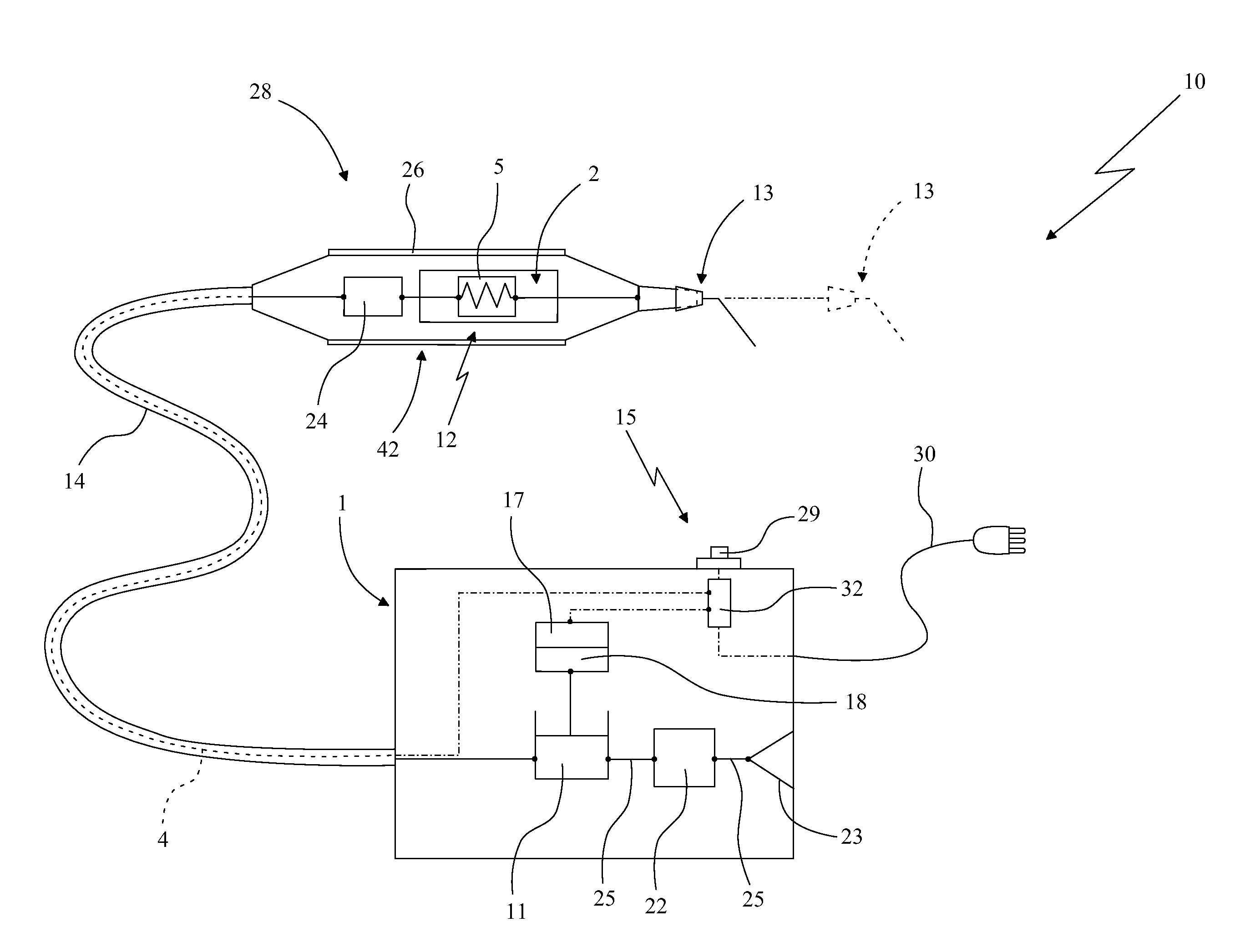
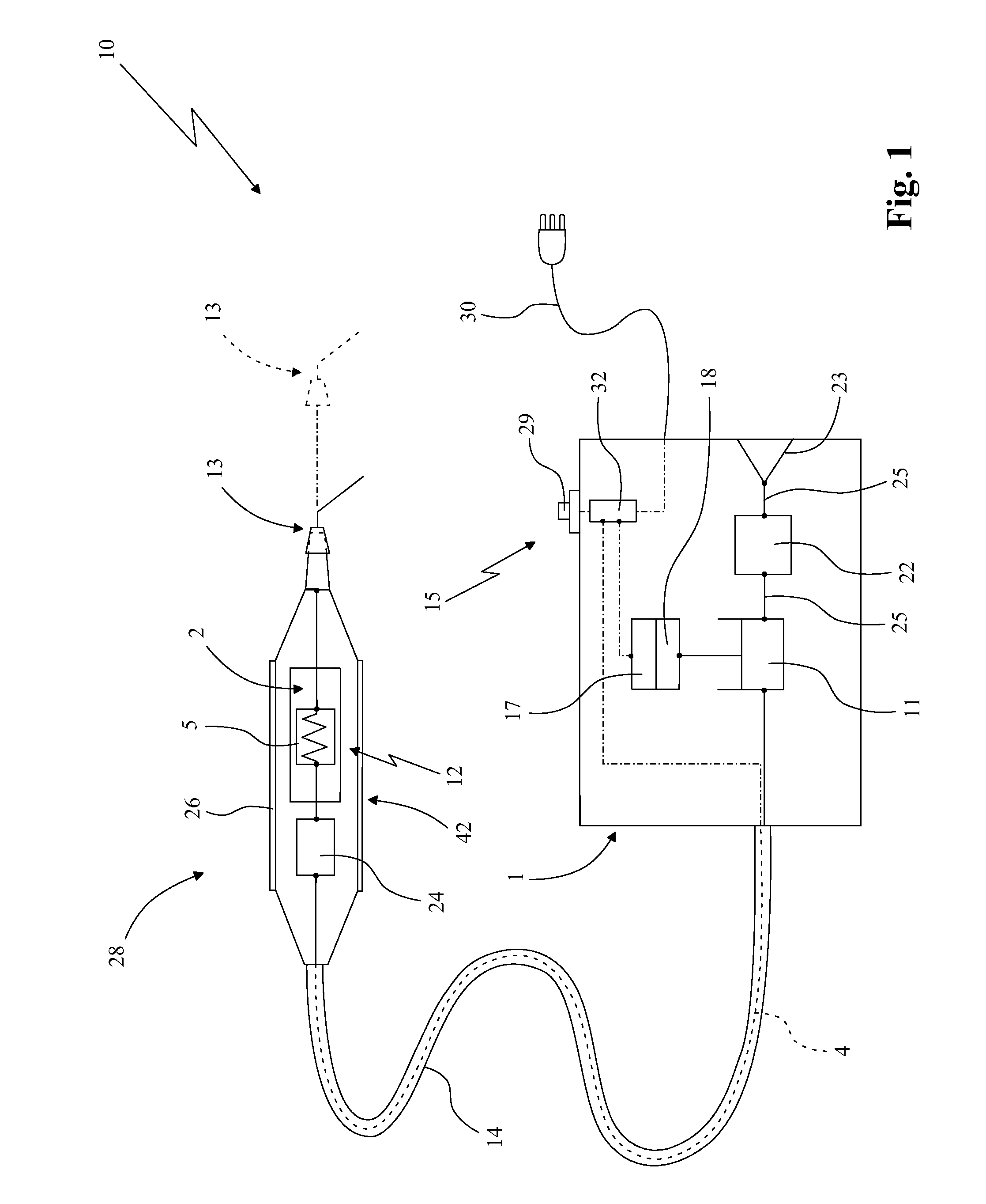
[0028]In accordance with the figures of the accompanying drawings, 10 denotes in its entirety the blower for dental use according to the present invention. This blower is intended to be used advantageously for drying a pulp canal of a tooth during endodontic surgery.

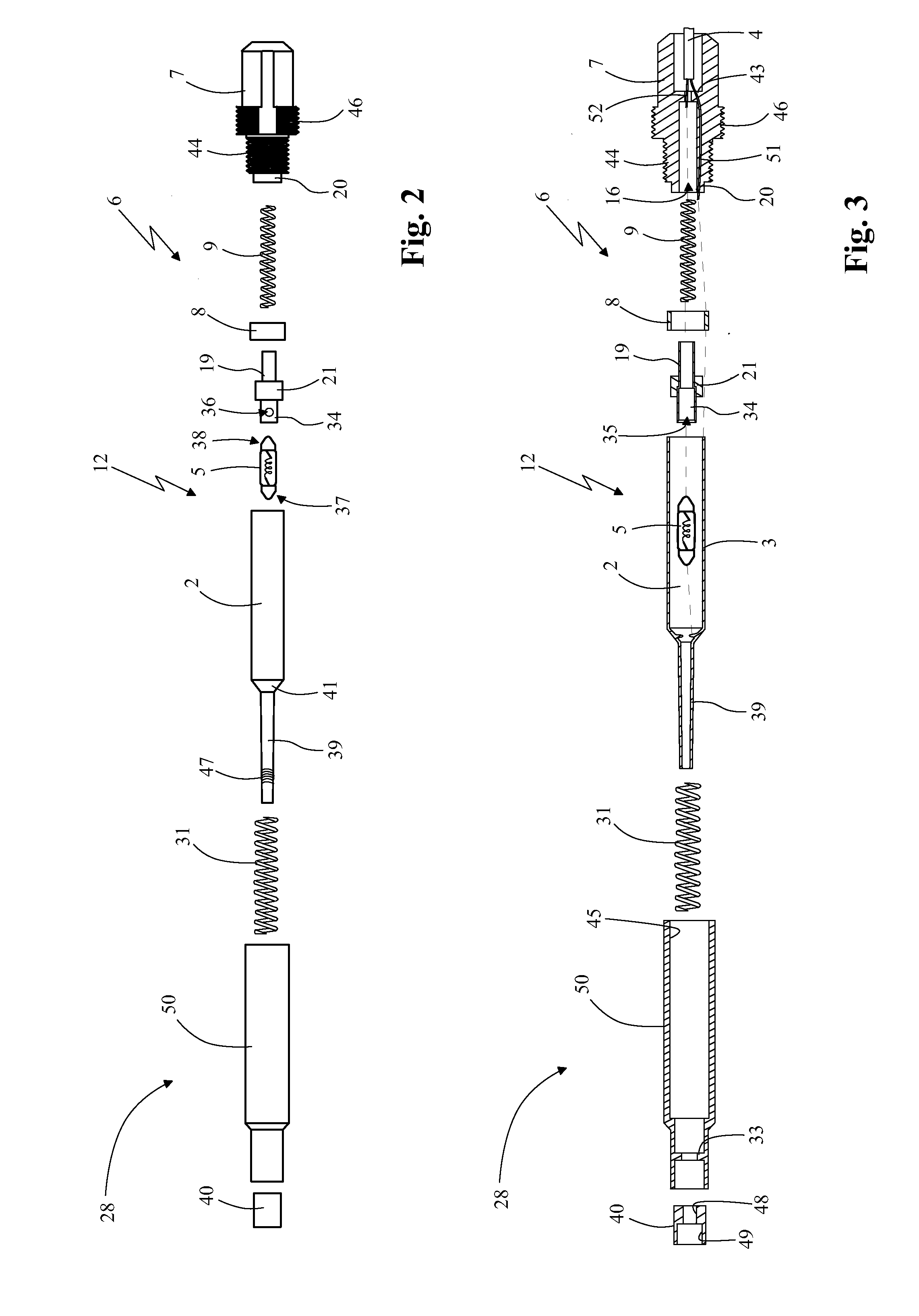
[0029]In accordance with the accompanying figures, the blower 10 comprises a support structure 1, which is advantageously box-shaped, an air source and a handpiece 28. The latter is connected to a pipe 14 supplying air to be blown in, which is produced by the air source, and a blowing nozzle 13 for the air received from the supply pipe 14. In greater detail, the handpiece 28 has a hollow support body 50 and is connected to the supply pipe 14 by means of a connector 7 which, in accordance with the embodiment shown in FIG. 2, has a first threaded portion 44 designed to engage with a corresponding first portion 45 with matching thread provided on the hollow body 50 of the handpiece 28.

[0030]The connector 7 also has a first ...


PUM


Abstract

A blower for dental use, which comprises a support structure (1), an air source and a handpiece (28). Said handpiece is connected to a pipe (14) supplying air to be blown in, which is produced by the air source, and a blowing nozzle (13) for the air received from the supply pipe (14).The blower 10 also comprises means (12) for heating the air to be blown in, which means are mounted within the handpiece (28) so as to heat the air received from the supply pipe (14) and release it, heated, to the blowing nozzle (13).The air source comprises a compressor (11) which is housed inside the support structure (1) and is connected to the handpiece (28) by means of the air supply pipe (14) and produces a constant air flow having a pressure when leaving the blowing nozzle (13) of between 0.1 and 1 bar. The blowing nozzle (13) has a maximum outer dimension ranging between 0.4 and 1.3 mm and is able to be inserted inside endodontic canals so as to inject the air expelled from it into endodontic canals, once inserted therein.

Description

FIELD OF APPLICATION[0001]The present invention relates to a blower for dental use, according to the preamble of the independent claim No. 1.[0002]The blower in question is intended to be used in the dental sector, in particular for drying the pulp canal of a tooth during endodontic surgery.[0003]During operation, the aforementioned blower is designed to emit a controlled air flow intended to be advantageously conveyed inside a pulp canal so as to dry the liquid present therein.BACKGROUND ART[0004]As is known, nowadays, in the dentistry sector, in order to dry endodontic canals, special-size, absorbent, paper cones are used. These cones, when inserted into the canal to be dried, absorb the liquid remaining there, drying the canal at least partially.[0005]These paper cones, however, in practice are not devoid of drawbacks. One major drawback is the fact that these paper cones have a limited drying efficiency. In order to remove completely the liquid present inside a canal, the dentis...

Claims


Application Information

Patent Timeline
Patent Type & Authority Applications(United States)
IPC IPC(8): A61C5/02A61C17/022A61C5/50
CPCA61C1/0069A61C17/022A61C5/04A61C5/50
Inventor COHEN, SIMONSPANO, ERNESTO
Owner SHIBRUN
Learn More