Separation purification method and microfluidic circuit
a technology of microfluidic circuit and separation method, which is applied in the direction of diaphragms, immobilised enzymes, dna preparation, etc., can solve the problems of high cost of reagents, reduced sensitivity, and difficulty in coping with ulterior advanced medical care and tailor-made medical care, so as to achieve accurate and rapid separation and easy purification
- Summary
- Abstract
- Description
- Claims
- Application Information
AI Technical Summary
Benefits of technology
Problems solved by technology
Method used
Image
Examples
example 1
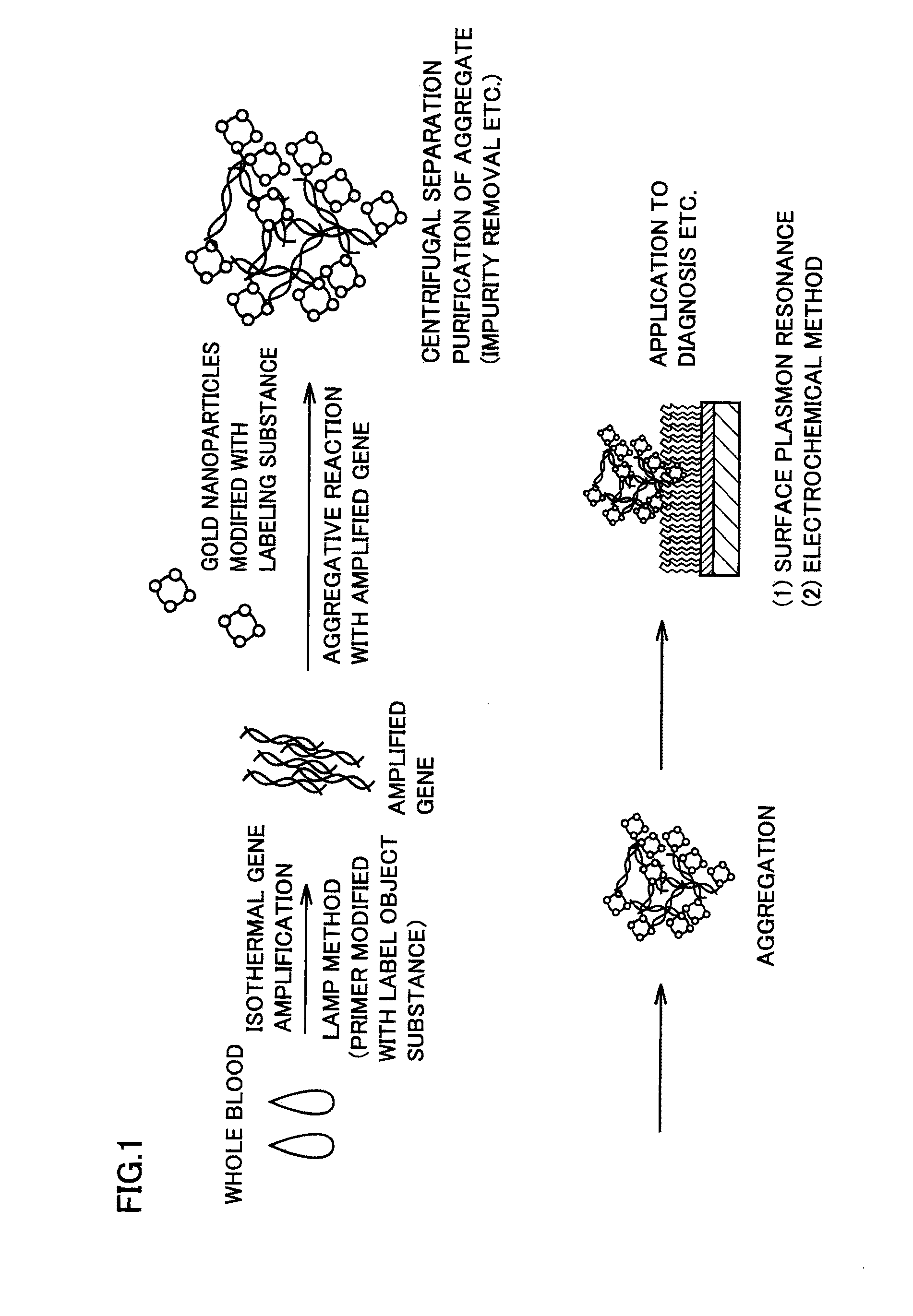
[0035]In this Example, a particulate aggregate was detected after performing separation purification of a cancer-derived amplified gene through a gold nanoparticle aggregative reaction. FIG. 1 shows the protocol of the reaction. As shown in FIG. 1, an amplified gene was formed by performing isothermal gene amplification on whole blood employed as a sample by the LAMP method with a primer modified with a label object substance, and a particulate aggregate was thereafter formed by reacting gold nanoparticles modified with a labeling substance and the amplified gene. Then, separation purification of the particulate aggregate was centrifugally performed for removing impurities, and the particulate aggregate was thereafter detected as such by surface plasmon resonance and the electrochemical method.
[0036]The gold nanoparticles were prepared from gold nanoparticles of 10 nm in average particle diameter modified with streptavidin which is the labeling substance specifically reacting with t...
example 2
[0066]In this Example, pepsinogen I which is one of cancer tumor markers was detected by an antigen-antibody reaction employing gold nanoparticles. Human serum was employed as a specimen, and gold nanoparticles of 20 nm in average particle diameter modified with a mouse monoclonal pepsinogen I antibody were employed as particulates specifically reacting with pepsinogen I in the specimen. When pepsinogen I was present in the specimen, the gold nanoparticles modified with the mouse monoclonal pepsinogen I antibody and pepsinogen I specifically reacted with each other and formed a particulate aggregate accompanied by a sandwich reaction. The color of the solution containing the particulate aggregate changed from red to purple due to the formation of the particulate aggregate. Thereafter the formed particulate aggregate was centrifugally separation-defined. The centrifugal separation purification was performed in an apparatus similar to that in Example 1 under a similar condition.
[0067]...
PUM
| Property | Measurement | Unit |
|---|---|---|
| Particle diameter | aaaaa | aaaaa |
| Particle diameter | aaaaa | aaaaa |
| Surface plasmon resonance | aaaaa | aaaaa |
Abstract
Description
Claims
Application Information
 - R&D
- Intellectual Property
- Life Sciences
- Materials
- Tech Scout
- Unparalleled Data Quality
- Higher Quality Content
- 60% Fewer Hallucinations
Browse by: Latest US Patents, China's latest patents, Technical Efficacy Thesaurus, Application Domain, Technology Topic, Popular Technical Reports.
© 2025 PatSnap. All rights reserved.Legal|Privacy policy|Modern Slavery Act Transparency Statement|Sitemap|About US| Contact US: help@patsnap.com


