Systems and methods for electric vehicle power flow management

a technology for electric vehicles and power flow management, applied in non-electric variable control, process and machine control, instruments, etc., can solve the problems of increasing energy waste, grid instability, and difficulty in moving away from carbon-intensive forms of electricity, so as to reduce the cost of providing power

Inactive Publication Date: 2011-01-06
GRIDPOINT
View PDF24 Cites 103 Cited by
  • Summary
  • Abstract
  • Description
  • Claims
  • Application Information

AI Technical Summary

Benefits of technology

The patent text describes a method for managing power flow using a power flow manager to coordinate charging activities of electrical devices. The method includes detecting system failure events and implementing a safe failure mode to provide predictable and non-disruptive coordination of charging activities. Additionally, the method includes using generation stacks of power production to reduce the cost of providing power to electrical devices and controlling a power production stack to order available power. A dispatchable load is listed in the power production stack, which is removed based on a cost reduction strategy. The technical effects of this patent text include improved management of power flow and cost reduction through efficient use of power production resources.

Problems solved by technology

The technical problem addressed in this patent text is the unreliability and antiquated infrastructure of the electric power grid, which leads to frequent power outages and wastes energy. The current power services infrastructure lacks provisioning and flexibility to aggregate a large number of small-scale resources, such as electric vehicle batteries, to meet large-scale needs of power services. Modern electric vehicles can benefit from a centrally controlled smart charging program, but more needs to be done to manage power flow at the local level and provide economical, reliable electrical power at times of peak demand. The patent text also highlights the need for power flow management systems and methods that manage power flow at the site-level, implement various power flow strategies for optimizing resource allocation, avoid power spikes, and minimize the total daily cost of providing energy generation.

Method used


Image

  • Systems and methods for electric vehicle power flow management
  • Systems and methods for electric vehicle power flow management
  • Systems and methods for electric vehicle power flow management

Examples


Embodiment Construction

[0028]Reference will now be made in detail to the embodiments of the present invention, examples of which are illustrated in the accompanying drawings.

[0029]Overview

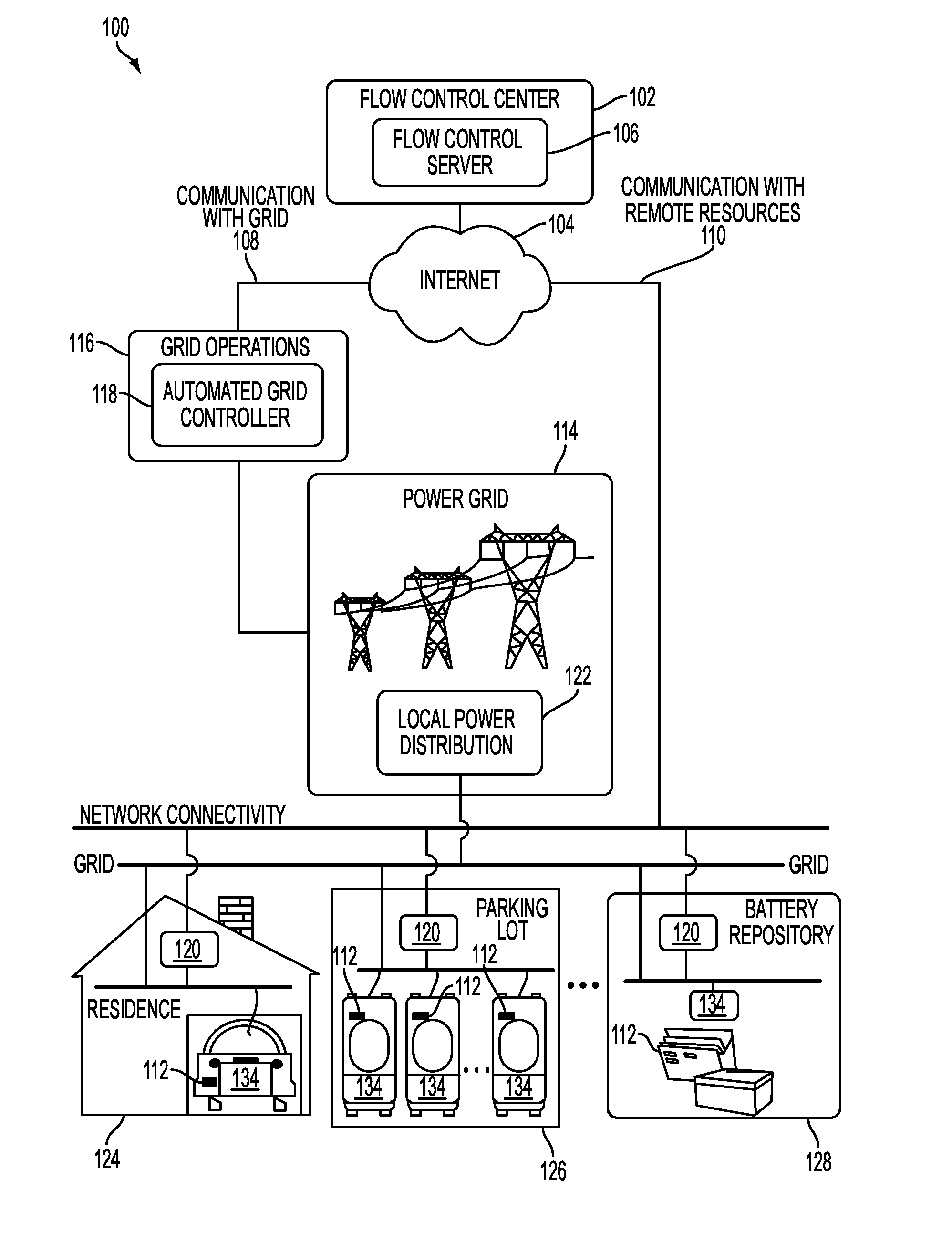
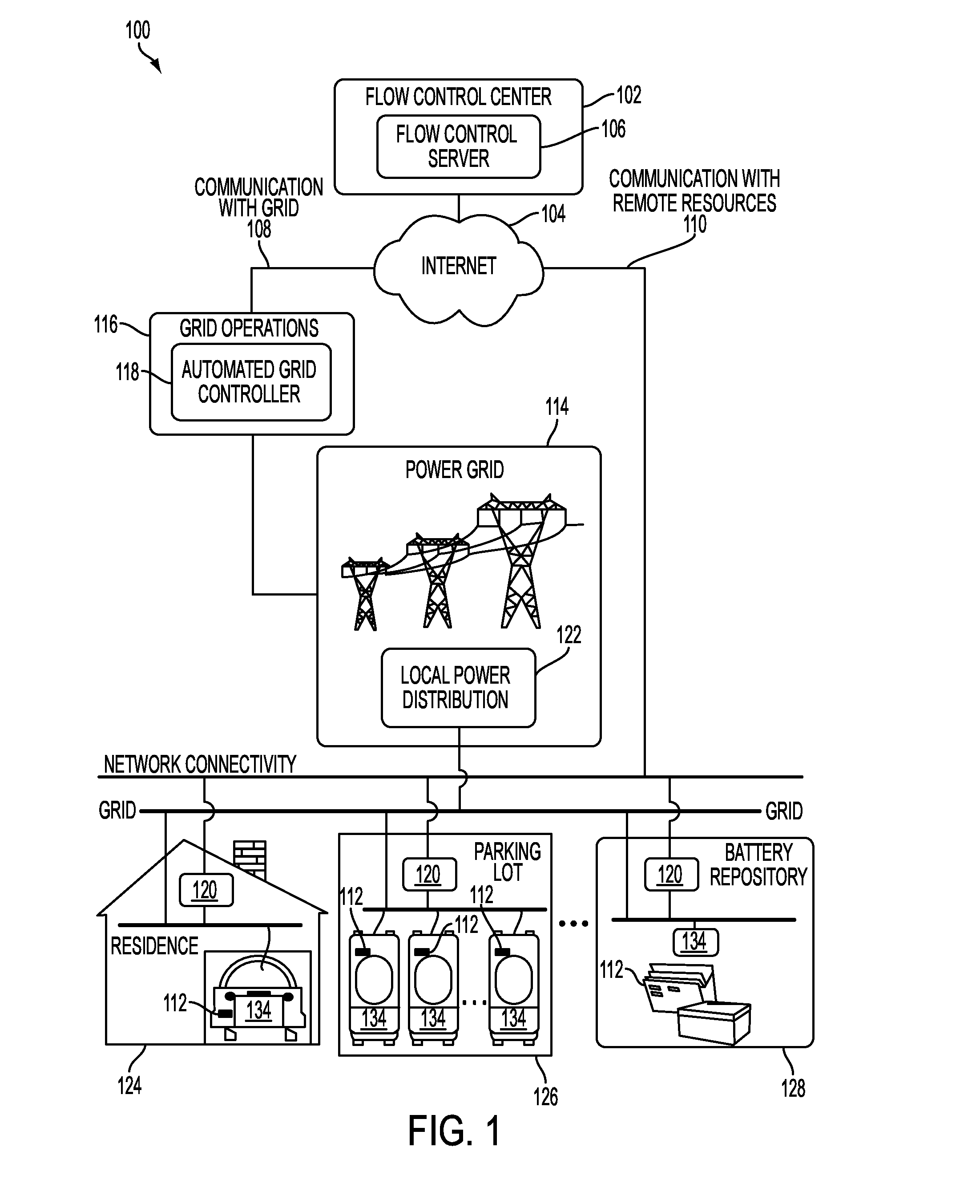
[0030]Described herein is a power aggregation system for distributed electric resources, and associated methods. In one implementation, a system communicates over the Internet and / or some other public or private networks with numerous individual electric resources connected to a power grid (hereinafter, “grid”). By communicating, the system can dynamically aggregate these electric resources to provide power services to grid operators (e.g. utilities, Independent System Operators (ISO), etc).

[0031]“Power services” as used herein, refers to energy delivery as well as other ancillary services including demand response, regulation, spinning reserves, non-spinning reserves, energy imbalance, reactive power, and similar products.

[0032]“Aggregation” as used herein refers to the ability to control power flows into and out of a s...


PUM


Abstract

A system and methods that enables power flow management at the local level. A power flow manager can coordinate the charging activities of electrical devices, such as electric vehicles. Power flow decisions may based on the site-level information. In addition, power flow management strategies may be optimized. An optimizer can choose a power flow management strategy and electrical devices for implementing a strategy. In the event of a system failure, power spikes may be avoided by using safe failure modes to provide that the charging activities be coordinated in a predictable and non-disruptive manner. The cost of providing power may be reduced using generation stacks of power production. As such, the total daily cost of providing energy generation may be minimized.

Description


Claims


Application Information

Patent Timeline
Owner GRIDPOINT
Why Eureka
Try Eureka