Device & method for filling multiple sandbags at a time

a technology of mechanical filling and sandbags, which is applied in the direction of flexible container closure, liquid handling, packaging goods types, etc., can solve the problems of limited number of proposals, limited access for towing or time required, and limited ability to back a dump truck close to the site of flooding

Active Publication Date: 2011-01-13
BARRIER SYST
View PDF10 Cites 11 Cited by
  • Summary
  • Abstract
  • Description
  • Claims
  • Application Information

AI Technical Summary

Benefits of technology

In a preferred embodiment, the bag-filling implement is held by attachment hooks along a back edge of the loader bucket and maneuvered by a hydraulic ram or a scoop component of the loader bucket. The apertures in each row are spaced in offset manner from those of the other rows. The trigger mechanisms of all of the apertures in each row are all aligned on the same side and rotated by a pivot shaft extending laterally across the surface width on the underside of the planar surface of the implement. The pivot shafts terminate in respective pivot gears which are engaged with a toothed rack or bar that is moved linearly bidirectionally by a hydraulic ram to turn the pivot gears in the desired rotational directions. In this manner, all of the sandbags can be cinched closed and released to the ground without the need for the intervention of workers, thereby ensuring their convenience and safety.

Problems solved by technology

However, the ability to back a dump truck close to the site of flooding may be limited by road accessibility and / or by the limited mobility of a dump truck.
However, this approach has problems of limited accessibility for towing or the time required for assembling a filling stand or conveyor equipment near a flood site.
While loader-type equipment has the desired mobility for maneuvering near a flood site for sandbag filling and piling, the prior proposals are limited in the number of bags that can be filled at a time from a loader bucket.

Method used


Image

  • Device & method for filling multiple sandbags at a time
  • Device & method for filling multiple sandbags at a time
  • Device & method for filling multiple sandbags at a time

Examples


Embodiment Construction

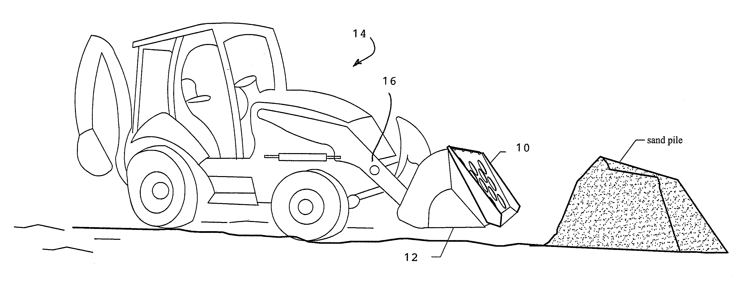
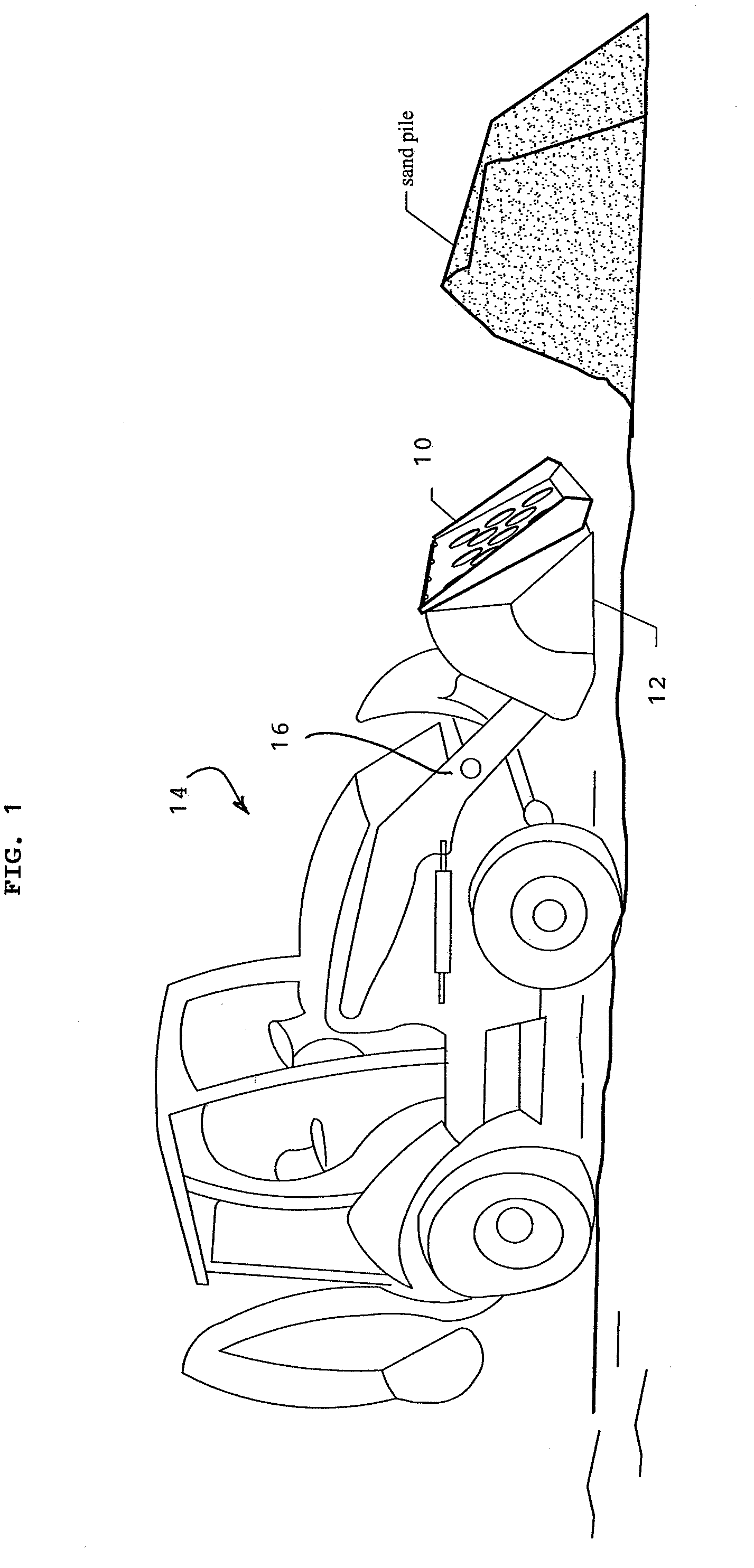
Referring to FIG. 1, a front loader is shown having a multi-bag filling implement 10 attached to the open end of a hydraulically actuated loader bucket 12 of an earthmover or loader-type equipment 14. The bag-filling implement 10 has multiple rows each with multiple filler apertures 10a spaced over its operative surface area. The loader-type equipment 14 has a high mobility of movement to scoop sand from a sand pile and push the sand onto the bag-filling implement 10 using its hydraulic arms 16 to manipulate the loader bucket 12. The loader equipment can then elevate the loader bucket with the bag-filling implement 10, and deposit the filled sandbags from the implement at the site where they are to be piled for flood control or simply drop them in offset rows in their final positions. This eliminates the need for laborers to engage in filling the sandbags by hand and carrying them to the site where they are to be piled.

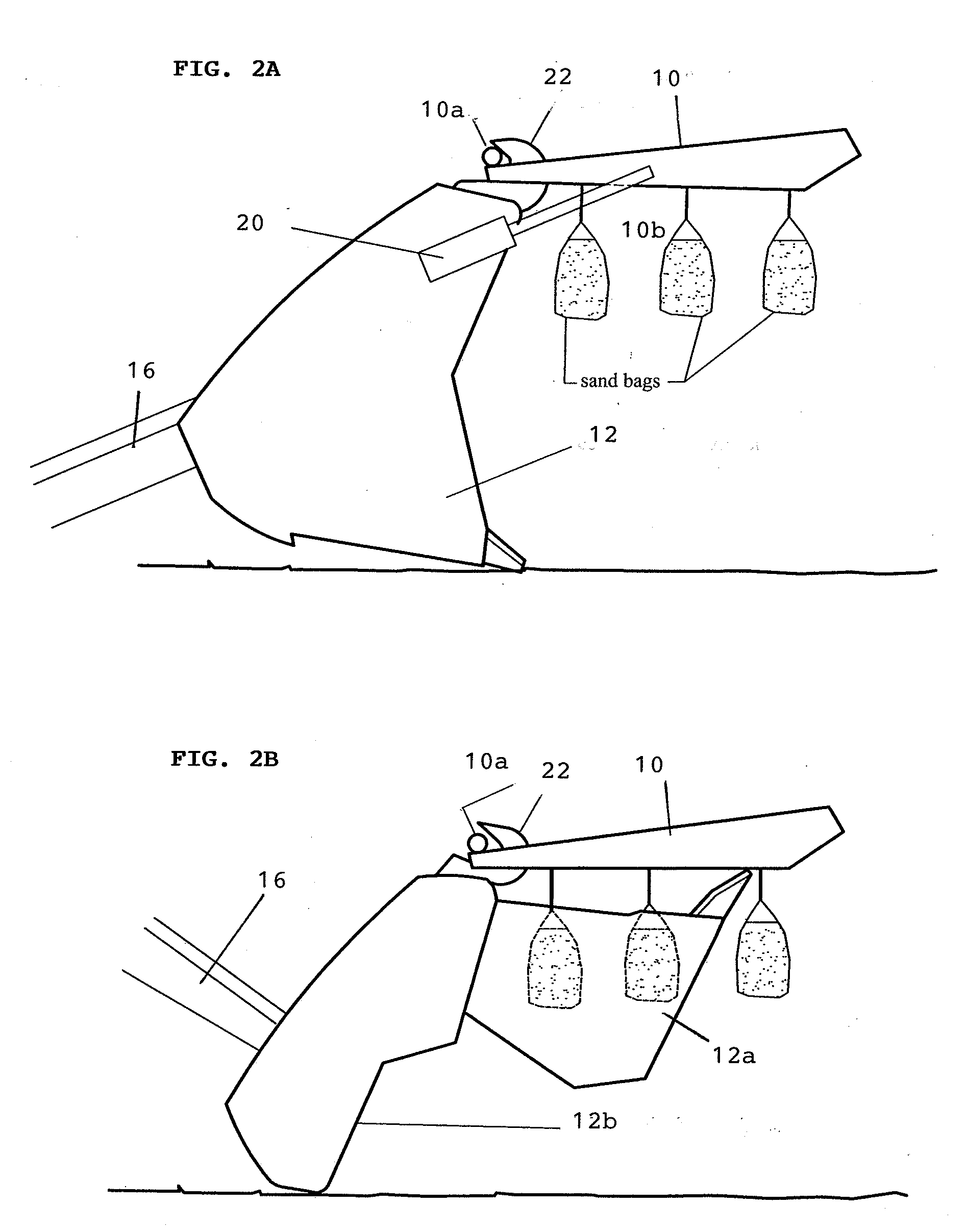
FIG. 2A illustrates the bag-filling implement 10 on a standard b...


PUM

PropertyMeasurementUnit
circumferential lengthaaaaaaaaaa
diameteraaaaaaaaaa
diameteraaaaaaaaaa

Abstract

An implement for mechanically filling multiple sandbags at a time is used on a loader bucket of loader-type equipment. The implement has a planar surface in which a plurality of filler apertures are formed in a plurality of rows evenly spaced over its surface area. Each filler aperture has a tensioner ring around the aperture for holding a drawstring held in a sleeve around an open end of the sandbag. A trigger mechanism is movable to a locked position in which the drawstring of the sandbag is pulled tight so that the open end of the sandbag is held in place on the tensioner ring, to an unlocked position in which the trigger mechanism lifts the drawstring off the tensioner ring to allow the sandbag filled with filler material to pull on and cinch the open end of the sandbag closed, and to a release position in which the cinched sandbag is released to the ground.

Description

FIELD OF INVENTIONThe present invention relates to a device and method for mechanically filling multiple sandbags at a time at a site where sandbags are to be piled for flood control, and particularly to a mechanical system that facilitates cinching the filled sandbags, positioning them to be dropped to the ground, and controlling the manner and timing with which they are dropped.BACKGROUND OF INVENTIONFor controlling unexpected floods, sand bags are commonly filled using shovels or hand implements so that they can be piled in massed piles or along makeshift revetments for flood control. Due to the hard labor required and the short time available in emergency conditions, it would be desirable to have a more convenient way to fill as many sandbags at a time as possible. Some prior systems have employed a sand hopper on the tailgate of the loader of a dump truck to fill sandbags, such as described in U.S. Pat. No. 3,602,402 to Garden, or U.S. Pat. No. 4,585,041 to Cavanaugh. However, ...

Claims


Application Information

Patent Timeline
Patent Type & Authority Applications(United States)
IPC IPC(8): B65B1/06B65B43/54B65D33/28
CPCB65B1/04B65B1/06E02F3/404B65B67/1222B65B43/54
Inventor HARTLEY, III, JOSEPH W.
Owner BARRIER SYST
Why Eureka
Try Eureka