Control method of sliding a vehicle door by a powered sliding device

a technology of sliding door and control method, which is applied in the direction of doors, pedestrian/occupant safety arrangements, tractors, etc., can solve the problems of low convenience, erroneous operation of the operating switch, and inability to move the sliding door by the powered sliding device, so as to ensure the safety of the sliding device and the convenience of operation

Inactive Publication Date: 2005-08-09
MITSUI KINZOKU ACT
View PDF6 Cites 12 Cited by
  • Summary
  • Abstract
  • Description
  • Claims
  • Application Information

AI Technical Summary

Benefits of technology

[0008]Therefore, it is an object of the present invention to provide a control method wherein at a vehicle speed of about 3 km / h or less, even if the foot brake or the parking brake is operated, the door opening operation of the sliding device is prohibited when the erroneous detection of the vehicle speed because of the lock of the wheel is expected, so that the convenience and the safety of the sliding device can be ensured.

Problems solved by technology

Therefore, the counter measure for the erroneous operation of the operating switch which may happen during the vehicle running is necessary.
This operating condition of the sliding device is excellent in terms of the safety, but is low in terms of the convenience.
For example, even if the vehicle is completely stopped by the foot brake, the movement of the sliding door by the powered sliding device cannot be performed when the shift lever is positioned in the drive position.
Furthermore, at low speeds it is difficult to instantly and accurately determine when a vehicle has come to a complete stop, and therefore, in the trade, the vehicle speed of about 3 km / h or less is regarded as the stopping of the vehicle.
The problem of the control method is that it is impossible to prevent the erroneous start of the sliding device when the wheel is locked.
Furthermore, at the vehicle spinning, there is such a risk that erroneous detection of the vehicle speed may happen.
Furthermore, at the vehicle spinning, such a risk that the person in the vehicle erroneously touches the operating switch is increased.

Method used


Image

  • Control method of sliding a vehicle door by a powered sliding device
  • Control method of sliding a vehicle door by a powered sliding device
  • Control method of sliding a vehicle door by a powered sliding device

Examples


Embodiment Construction

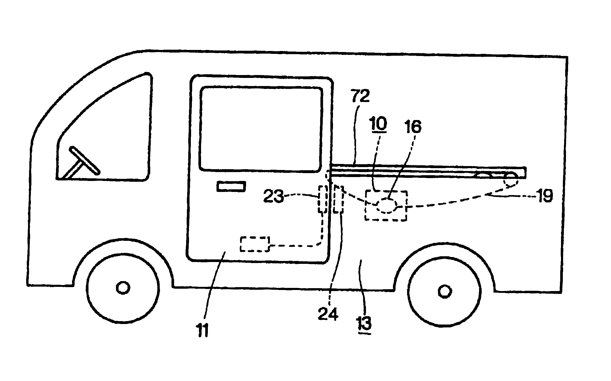
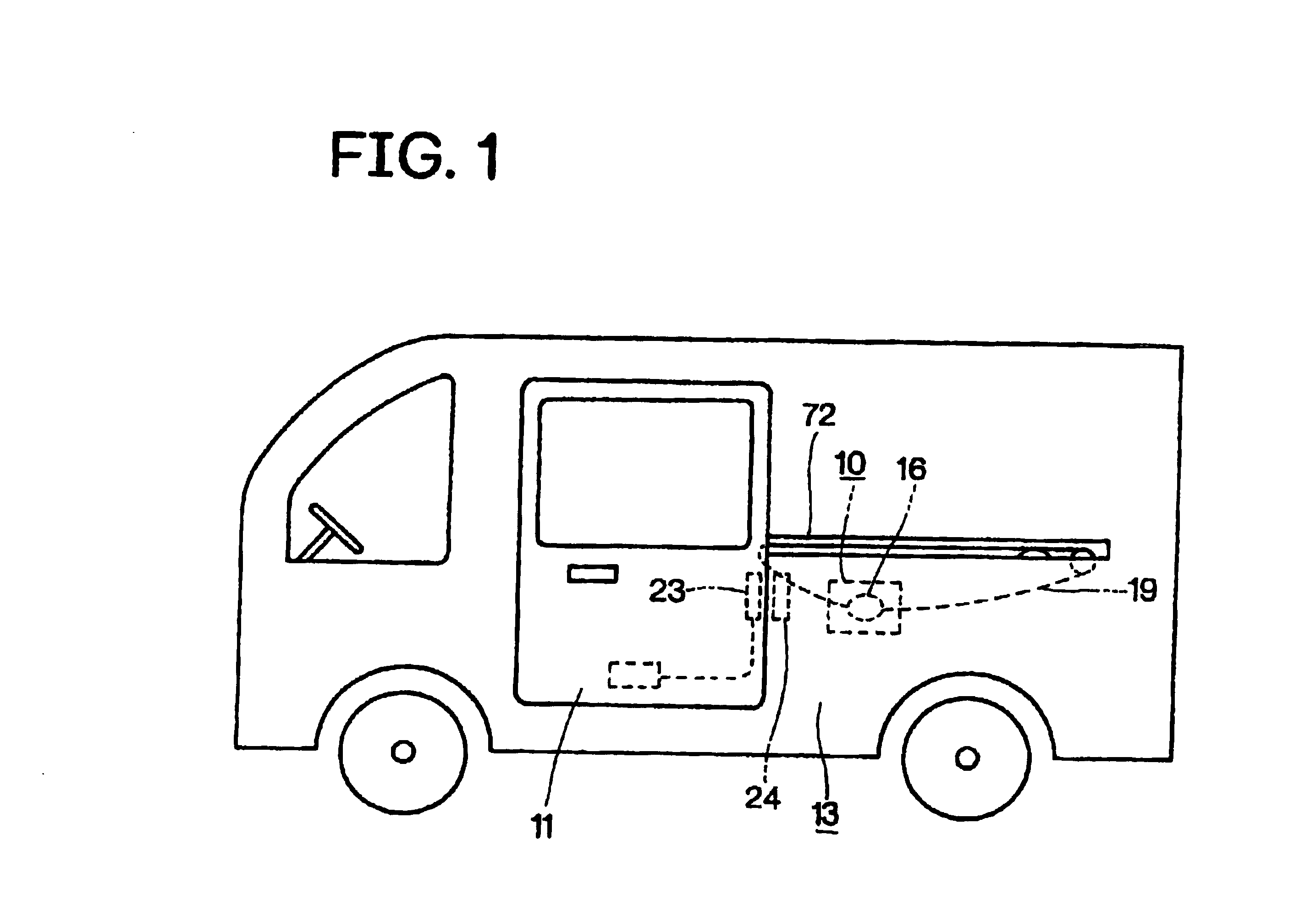
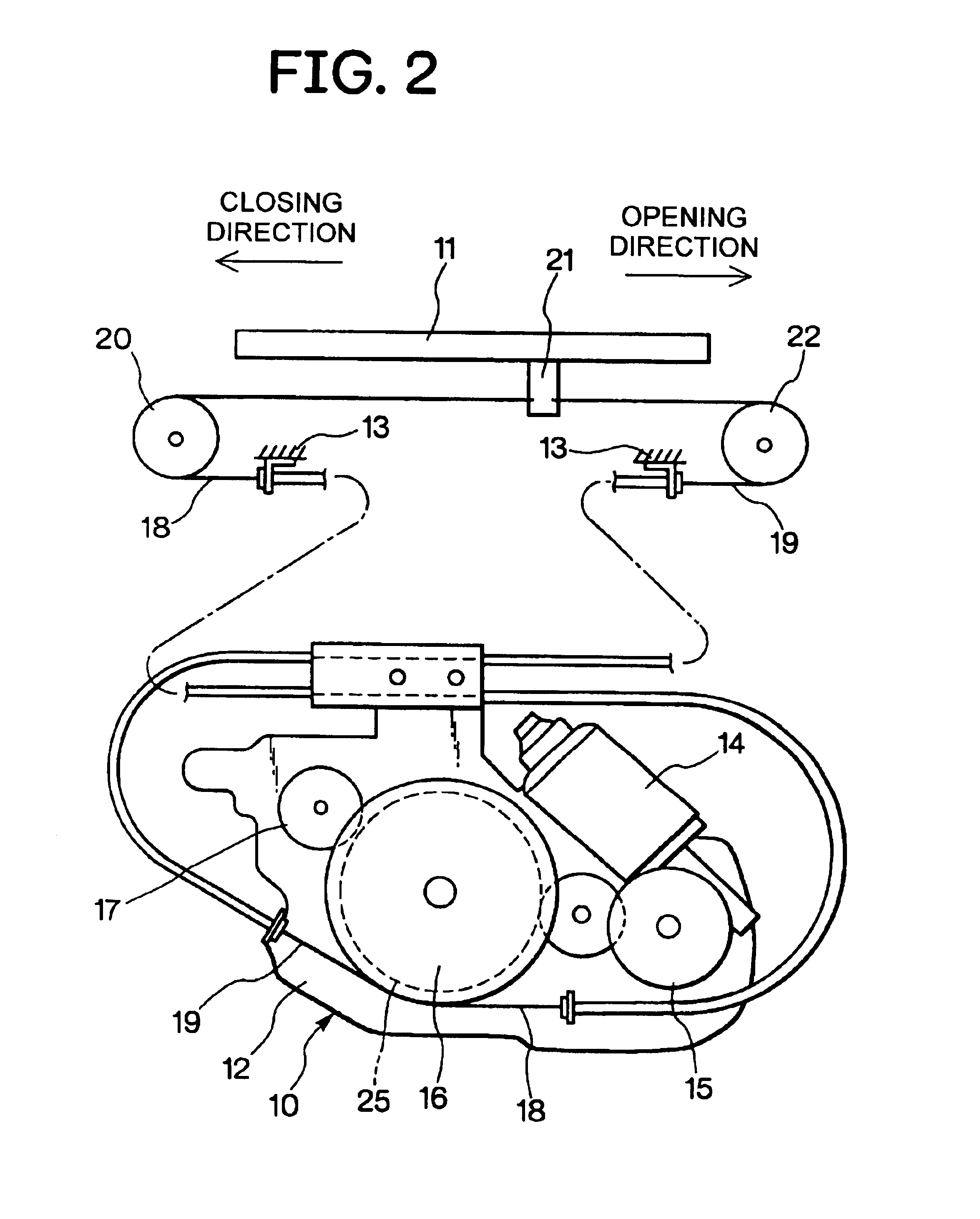
[0013]One embodiment of the present invention will be described by using drawings. FIG. 1 shows the rough relation between a powered sliding device 10 according to the present invention and a vehicle sliding door 11 which slides in the door closing direction and in the door opening direction by the powered sliding device 10, and FIG. 2 shows the expanded relation between the two.

[0014]The sliding door 11 is slidably attached to a vehicle body 13, and is slidable in the back and forth direction of the vehicle body 13 along a guide rail 72 provided to the vehicle body 13. A base plate 12 of the powered sliding device 10 is fixed to the vehicle body 13, and to the base plate 12, a motor 14, a reduction mechanism 15, a wire drum 16, and an electromagnetic brake 17 are provided. The electromagnetic brake 17 is operated by the electric control, and applies braking to the wire drum 16.

[0015]To the wire drum 16, one end sides of two wire cables 18, 19 are connected. The other end side of th...


PUM


Abstract

A control method of a powered sliding device for a vehicle sliding door, wherein when an operating switch for starting a powered sliding device is pressed to open the door, and if the vehicle speed is about 3 km/h or less and the foot brake or the parking brake is operated, the decelerating state of the vehicle just before is confirmed, and when the decelerating state does not correspond to the quick braking, the powered sliding device is started.

Description

BACKGROUND OF THE INVENTION[0001]1. Field of the Invention[0002]The present invention relates to a control method of a powered sliding device for a vehicle sliding door.[0003]2. Description of the Related Art[0004]Conventionally, a powered sliding device for a vehicle sliding door where the sliding door is slid in the door closing direction and in the door opening direction by rotating a wire drum connected through a wire cable to a sliding door with the power of a motor is well known.[0005]The sliding device is started by the operation of one or a plurality of operating switches provided in the vehicle, and opens and closes the sliding door. Therefore, the counter measure for the erroneous operation of the operating switch which may happen during the vehicle running is necessary. In the vehicle to North America, it is set that the door opening operation of the sliding door is prohibited except when the shift lever of the automatic transmission is positioned at the parking position....

Claims


Application Information

Patent Timeline
Patent Type & Authority Patents(United States)
IPC IPC(8): E05F15/14E05F15/20B60J5/06E05F15/00
CPCE05F15/70E05F15/40E05F15/632E05Y2201/21E05Y2201/654E05Y2201/664E05Y2400/52E05Y2900/531E05F15/646E05Y2800/254
Inventor YOKOMORI, KAZUHITO
Owner MITSUI KINZOKU ACT
Why Eureka
Try Eureka