Fluorescent imaging device

Active Publication Date: 2019-08-15
SHIMADZU CORP
View PDF0 Cites 5 Cited by
  • Summary
  • Abstract
  • Description
  • Claims
  • Application Information

AI Technical Summary

Benefits of technology

[0022]In the aforementioned fluorescent imaging device according to this aspect, the third light source is preferably configured to radiate the non-visible light in a wavelength range that overlaps with a wavelength of the fluorescence, and the imager preferably includes a first imaging element for capturing the fluorescent image and the non-visible image and a second imaging element for capturing the visible image. According to this structure, using the wavelength range in which the wavelength of the fluorescence and the wavelength of the non-visible light overlap with each other, both the fluorescent image and the non-visible image can be captured by the common imaging element. Consequently, even when all of the fluorescent image, the non-visible image, and the visible image are captured, the device structure can be simplified.
[0023]In the aforementioned fluorescent imaging device according to this aspect, the third light source is preferably configured to radiate the non-visible light, which substantially excludes a wavelength range of light of a fluorescent lamp. In the present specification, the phrase “excludes (not including) a wavelength range of light of a fluorescent lamp” indicates that when the spectra of the third light source and the fluorescent lamp are compared, the spectra of the third light source and the fluorescent lamp do not overlap with each other at least in the wavelength range of half width (full width at half maximum), and it is allowed that the wavelength ranges of wavelength components of low intensity such as 20% or less of the peak intensity overlap with each other. Accordi

Problems solved by technology

However, when the moving-body tracking processing is performed in the fluorescent imaging device, there are the following problems.
When luminescent spots occur at the observation site, an image of the o

Method used


Image

  • Fluorescent imaging device
  • Fluorescent imaging device
  • Fluorescent imaging device

Examples


first embodiment

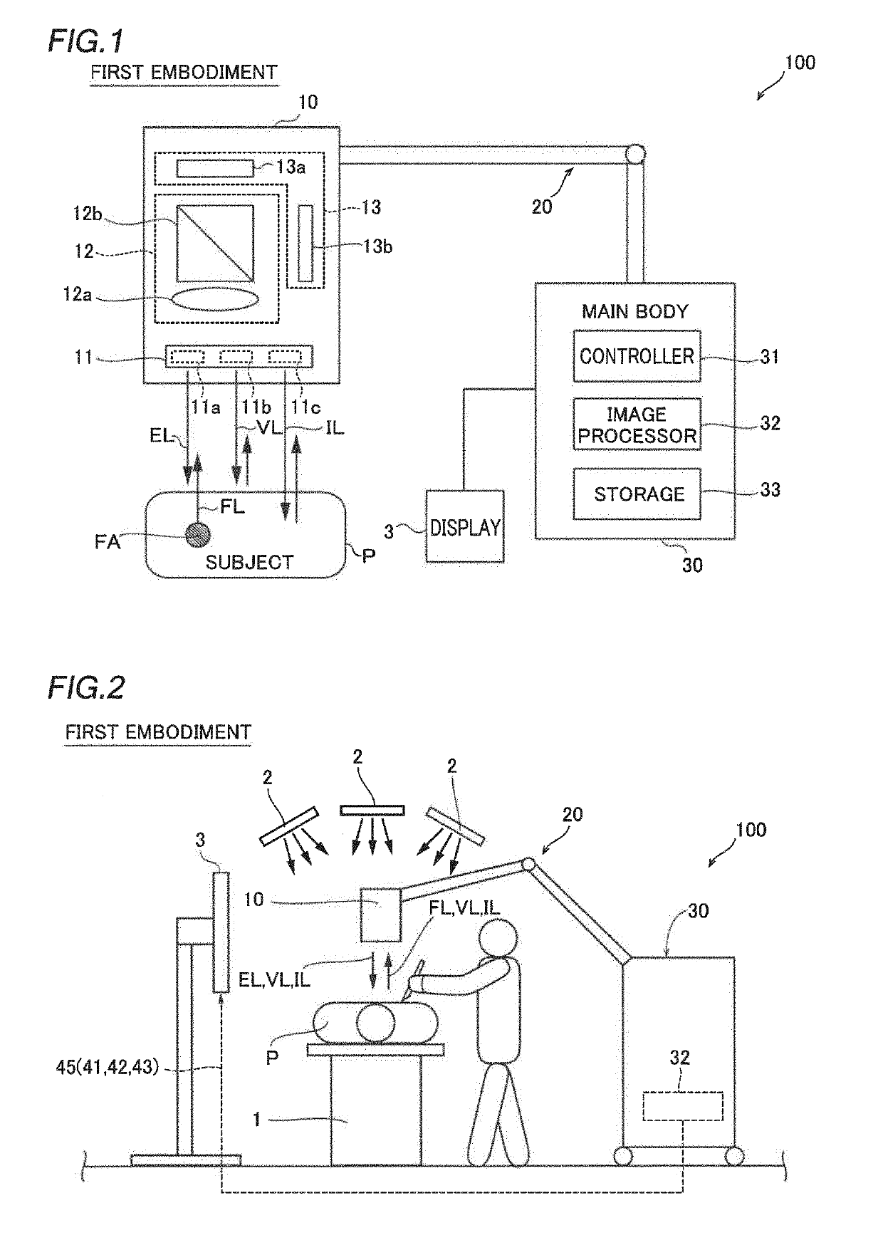
[0051]The structure of a fluorescent imaging device 100 according to a first embodiment of the present invention is now described with reference to FIGS. 1 to 11.

[0052]As shown in FIG. 1, the fluorescent imaging device 100 according to the first embodiment radiates excitation light EL to detect fluorescence FL emitted from a fluorescent agent FA administered to a subject P and visualizes (images) an observation site of the subject P based on the fluorescence FL. In the first embodiment, the fluorescent imaging device 100 that images the observation site from the outside of the subject P by an imager 10 spaced apart from the subject P is described. The subject P is a living body, and a living body of a human, for example. The subject P may be a living body of a small animal such as a mouse.

[0053]As shown in FIG. 2, the fluorescent imaging device 100 is used to check an observation site in surgical operations, for example. As an example, the fluorescent imaging device 100 used for car...

second embodiment

[0124]A second embodiment of the present invention is now described with reference to FIG. 16. In the second embodiment, a fluorescent imaging device 200 includes an endoscopic device 110, unlike the first embodiment in which imaging is performed from the outside of the subject P. The same structures as those of the first embodiment are denoted by the same reference numerals, and description thereof is omitted.

[0125]As shown in FIG. 16, the fluorescent imaging device 200 according to the second embodiment includes the endoscopic device 110 including a light source 11 and an imager 10. The fluorescent imaging device 200 further includes a main body 30 connected to the endoscopic device 110.

[0126]The endoscopic device 110 includes a flexible and deformable cable 120. The cable 120 is connected to the light source 11 and the imager 10 at branched root portions 111. A distal end 112 of the cable 120 is inserted into a subject P and is carried to the vicinity of an observation site insid...

modified examples

[0138]The embodiments disclosed this time must be considered as illustrative in all points and not restrictive. The scope of the present invention is not shown by the above description of the embodiments but by the scope of claims for patent, and all modifications (modified examples) within the meaning and scope equivalent to the scope of claims for patent are further included.

[0139]For example, while the analysis processor 32h that analyzes the flow of the fluorescent agent FA is provided in each of the aforementioned first and second embodiments, the present invention is not restricted to this.

[0140]According to the present invention, the analysis processor 32h may not be provided. The moving-body tracking is useful not only to analyze the flow of the fluorescent agent FA but also to specify an excision site on an image at the time of biopsy and to specify a treatment site, for example.

[0141]While as the analysis of the flow of the fluorescent agent FA, the analysis processor 32h ...


PUM


Abstract

A fluorescent imaging device includes a light source unit including a first light source for radiating excitation light, a second light source for radiating visible illumination light, and a third light source for radiating non-visible light, an imager being configured to capture a fluorescent image, a visible image, and a non-visible image, and a tracking processor that is operable to perform moving-body tracking for a region of interest that is set in an image based on at least the non-visible image.

Description

CROSS-REFERENCE TO RELATED APPLICATIONS[0001]This application claims the benefit of priority to Japanese Patent Application No. 2018-021597 filed on Feb. 9, 2018. The entire contents of this application are hereby incorporated herein by reference.BACKGROUND OF THE INVENTIONField of the Invention[0002]The present invention relates to a fluorescent imaging device, and more particularly, it relates to a fluorescent imaging device that captures an image with a fluorescent agent administered to a subject Description of the Background Art A fluorescent imaging device that captures an image with a fluorescent agent administered to a subject is known in general, as disclosed in Japanese Patent No. 4745059, for example.[0003]Japanese Patent No. 4745059 discloses a lymph node detecting apparatus (fluorescent imaging device) that radiates excitation light to a living body observation portion including lymph nodes into which a fluorescent agent is injected in advance and captures a fluorescent ...

Claims


Application Information

Patent Timeline
IPC IPC(8): A61B34/20G06T7/246A61B1/06A61B1/04A61B1/00
CPCA61B34/20G06T7/248A61B1/0653A61B1/043A61B1/00096A61B1/0638A61B1/00045G06T2207/10064G06T2207/10048G06T2207/30048G06T2207/30104A61B2034/2057A61B5/7425A61B5/0033A61B5/0071A61B5/1128A61B5/14556
Inventor IKEHARA, TATSUYA
Owner SHIMADZU CORP
Why Eureka
Try Eureka