
Pneumatic tire

a pneumatic tire and tire body technology, applied in the field of pneumatic tires, can solve the problems of insufficient wear resistance, and high load of pneumatic tires for heavy loads

Active Publication Date: 2011-01-13
BRIDGESTONE CORP
View PDF11 Cites 16 Cited by
  • Summary
  • Abstract
  • Description
  • Claims
  • Application Information

AI Technical Summary

Benefits of technology

[0007]An object of the present invention is to provide a pneumatic tire in which the tread pattern is optimized to enhance uneven wear resistance and elongate

Problems solved by technology

However, load of the pneumatic tire for heavy load is relatively high with respect to the pneumatic tire of the normal vehicle, and due to this, the wear resistance is not sufficient.
Therefore, when a tire is rotated with a load applied thereon, the wear speed is fast and tire life is short.
However, when such pneumatic tire is attached onto the vehicle as a driving wheel which transmits driving force, and when transmitting driving force to the road surface and the friction force burdened from road surface to the tread portion is larger in area at a tread ground end with respect to the area at the tire equatorial plane of the tread ground area, and therefore, area at a tread ground end will wear faster than the area at the tire equatorial plane, and uneven wear occurs to the tread portion as a whole.
On the other hand, when such pneumatic tire is attached onto the vehicle as a wheel which do not transmit driving force, and when transmitting driving force to the road surface and the friction force burdened from road surface to the tread portion is larger in area at a tire equatorial plane with respect to the area at the tread ground end of the tread ground area, and therefore, area at a tire equatorial plane will wear faster than the area at the tread ground end, and uneven wear occurs to the tread portion as a whole.
In view of this, uneven wear will result in the problem of reducing tire life.

Method used


Image

  • Pneumatic tire
  • Pneumatic tire
  • Pneumatic tire

Examples


examples

[0066]Next, tire having the conventional tread pattern (Conventional tire) and tire having tread pattern according to the present invention (Examples tires) were prepared at the size of 46 / 90R57 as a tire for the heavy load and the performances thereof were evaluated, respectively. Details thereof will be described below.

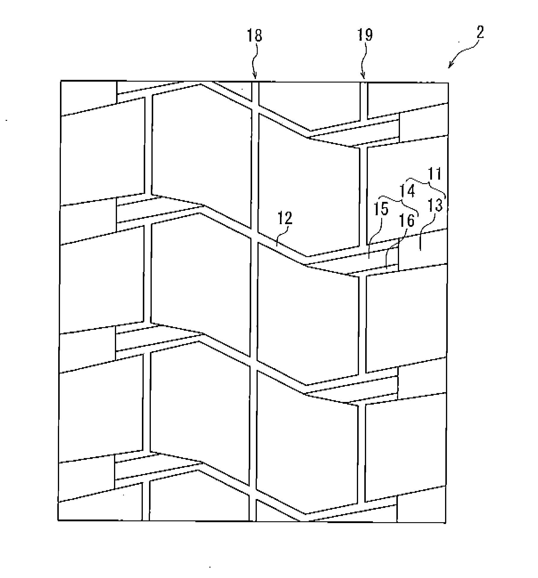
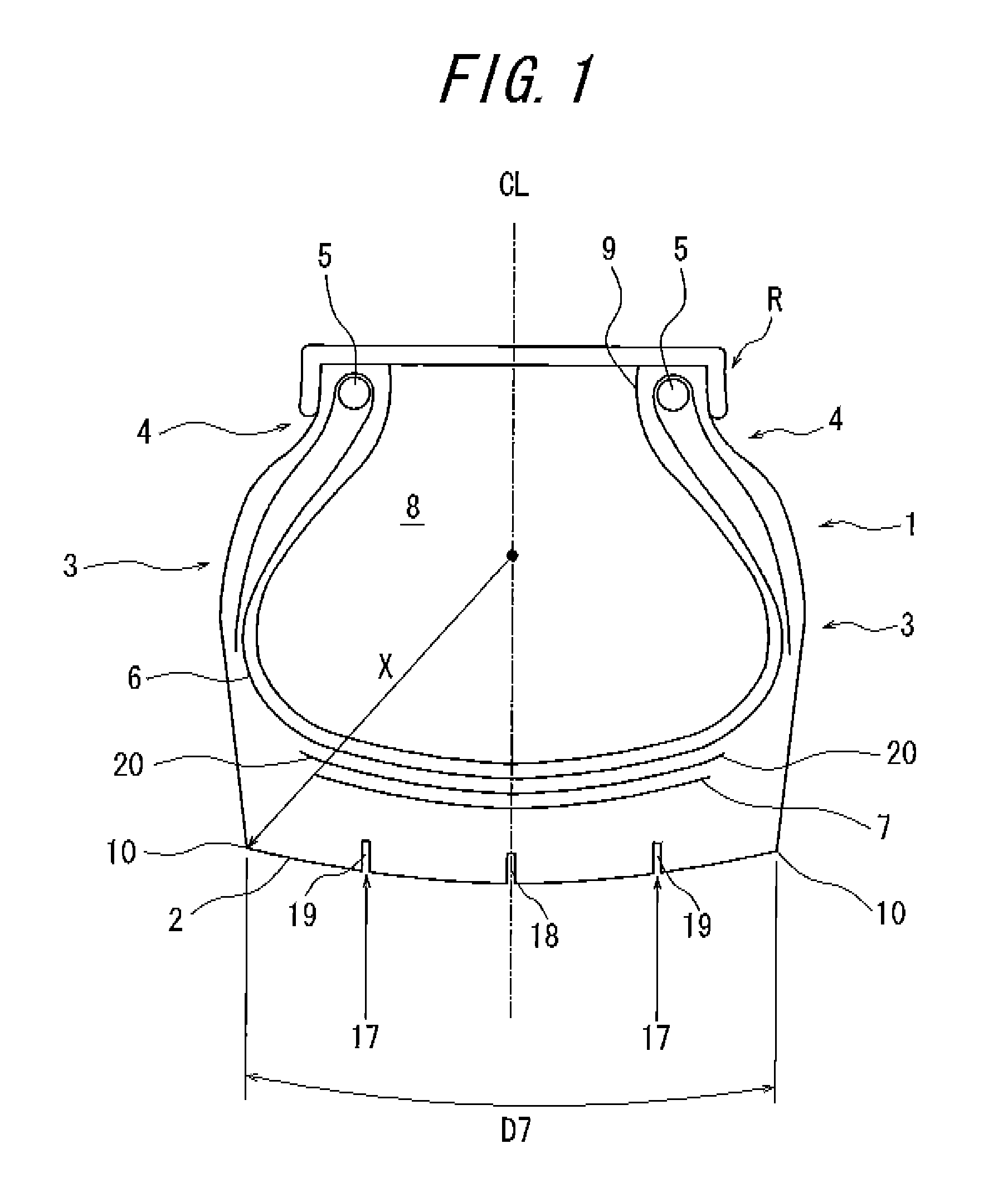
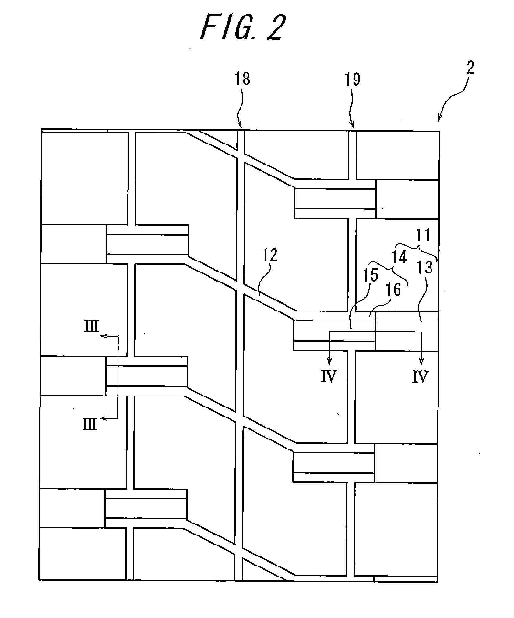
[0067]Conventional tire has narrow groove and lag groove with uniform depth in the tread portion, and has characteristics as shown in Table 1. Example tire has a lag groove that is composed of a first lag groove portion located on the outer side in the tire widthwise direction and a second lag groove portion located on the inner side in the tire widthwise direction, and a narrow groove. The first lag groove extend, in a sectional view in the tire widthwise direction, in the range of 20 to 25% with respect to the tread width, from the tread end toward the tire equatorial plane in the tire widthwise direction. The second lag groove portion extend, in a sectional view ...


PUM


Abstract

The present invention provides a pneumatic tire in which the tread pattern is optimized to improve wear resistance. The pneumatic tire has a tread portion embedding belt layer therein, wherein the tread portion has plural rows of lag grooves extending from the tread end to a tire equatorial plane and a narrow groove connecting the end of two lag grooves clipping the tire equatorial plane, wherein the narrow groove will be closed when contacting the road surface, wherein said lag groove is composed of a first lag groove portion located on the outer side in the tire widthwise direction and a second lag groove portion located on the inner side in the tire widthwise direction, wherein the maximum depth of the second lag groove portion is larger than the maximum depth of the first lag groove portion, wherein the second lag groove portion, in a sectional view in the tire circumferential direction, is composed of a shallow groove portion and deep groove portion having a larger depth than the shallow groove portion notching a part of the shallow groove portion, wherein the length in the tire circumferential direction of the deep groove portion is smaller than the length in the tire circumferential direction of the shallow groove portion.

Description

TECHNICAL FIELD[0001]The present invention relates to a pneumatic tire having a tread portion embedding belt layer therein, wherein the tread portion has plural rows of lag grooves extending from the tread end to a tire equatorial plane and a narrow groove connecting corresponding ends of two lag grooves on both sides of the tire equatorial plane, wherein the narrow groove will be closed when contacting the road surface and, in particular, a tire for heavy load. The present invention aims at enhancing wear resistance of such pneumatic tire.PRIOR ART[0002]In general, the pneumatic tire for heavy load has a rigid belt which enables the supporting of relative weight. Moreover, it is tended that the lag groove is arranged on the tread portion enable the traveling in various condition.[0003]In the pneumatic tire for heavy load having such tread pattern, rigidity of belt is enhanced to enhance the rigidity of tread portion as a whole, to inhibit the wear. However, load of the pneumatic ti...

Claims


Application Information

Patent Timeline
Patent Type & Authority Applications(United States)
IPC IPC(8): B60C11/13
CPCB60C2200/06B60C11/0316B60C11/0311B60C2200/065
Inventor MORI, ARATA
Owner BRIDGESTONE CORP
Learn More