Advanced immersive visual display system

a visual display system and advanced technology, applied in the field of 3d imaging display devices, can solve the problems of reducing performance, affecting the observer, and limiting the stereoscopic view,

Inactive Publication Date: 2011-01-13
SOLOMON DENNIS J
View PDF8 Cites 184 Cited by
  • Summary
  • Abstract
  • Description
  • Claims
  • Application Information

AI Technical Summary

Benefits of technology

[0008]Another object of the present invention is an improved method and device which permits image 3D pixel sources to be arranged orthogonally to image plane thereby enabling the display of an undistorted orthogonal surface or translucent solid,
[0011]Another object of the present invention is an improved method and device for constructing an accurate, augmented reality, visual display where the principal scene object axis converge at a virtual point in a plane behind that describe by the lens of the eye.

Problems solved by technology

These inventions have provided practical solutions to the problem of providing lightweight, high resolution displays but are limited to providing a stereoscopic view by means of image disparity.
It is well known in the field that wavefront-based technologies, which by definition are limited to coherent effects, impart significant specular and other aberrations degrading performance and inducing observer fatigue.
Despite the improvements during the past decade, the significant problem of providing a low cost, highly accurate visual display with full accommodation remains.
One of the principal limitations has been the inability of sequentially resonant or programmed variable focal length optics combined with scanning configurations to properly display solid three dimensional pixels, orthogonal to the scanning plane.
Another limitation is the inability of the observer's eye to properly and comfortably focus on rapidly flashing elements.
Numerous inventions have been proposed which have generally been too complicated to be reliable, too expensive to manufacture, without sufficient resolution, accuracy, stability to gain wide acceptance.

Method used


Image

  • Advanced immersive visual display system
  • Advanced immersive visual display system
  • Advanced immersive visual display system

Examples


Embodiment Construction

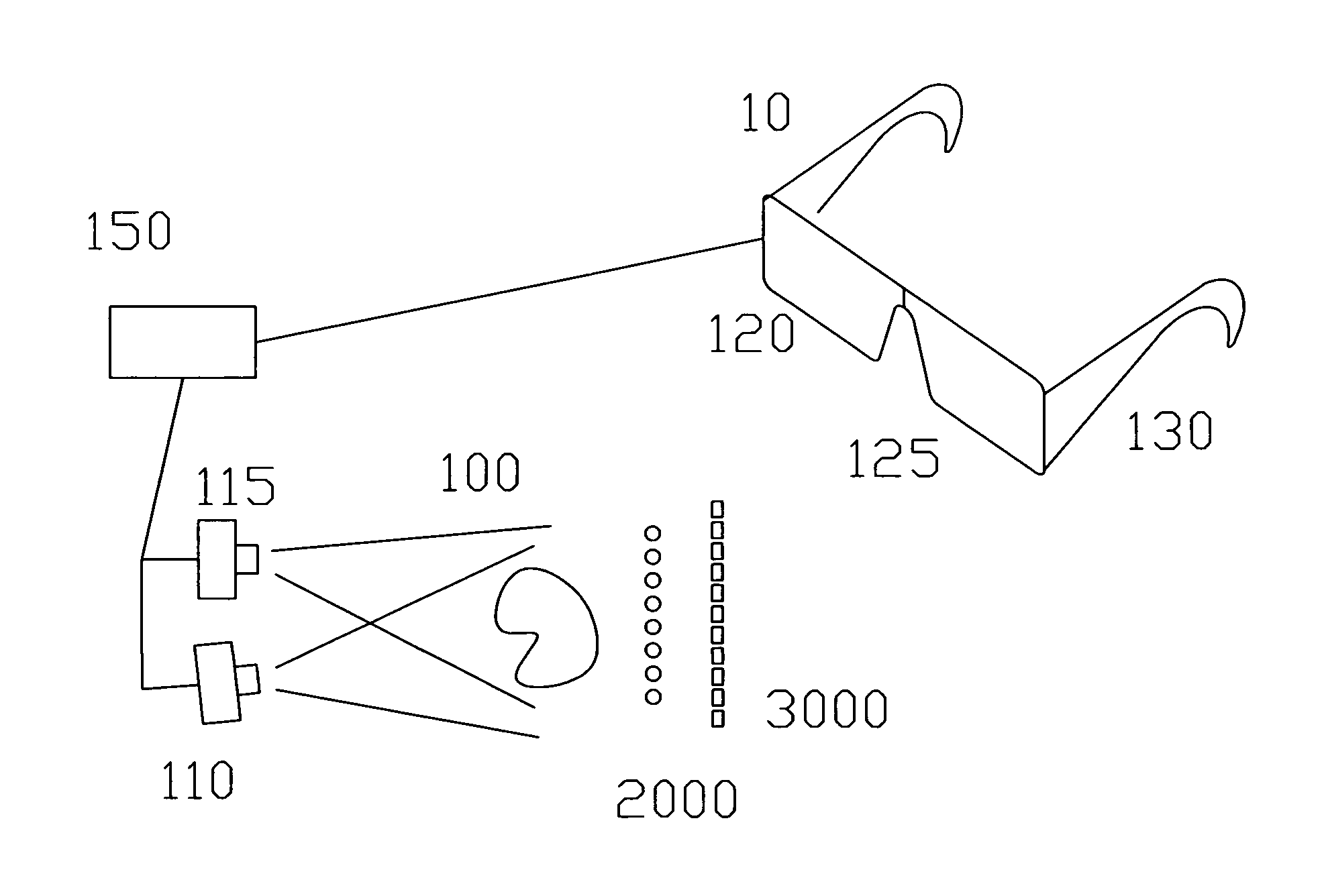
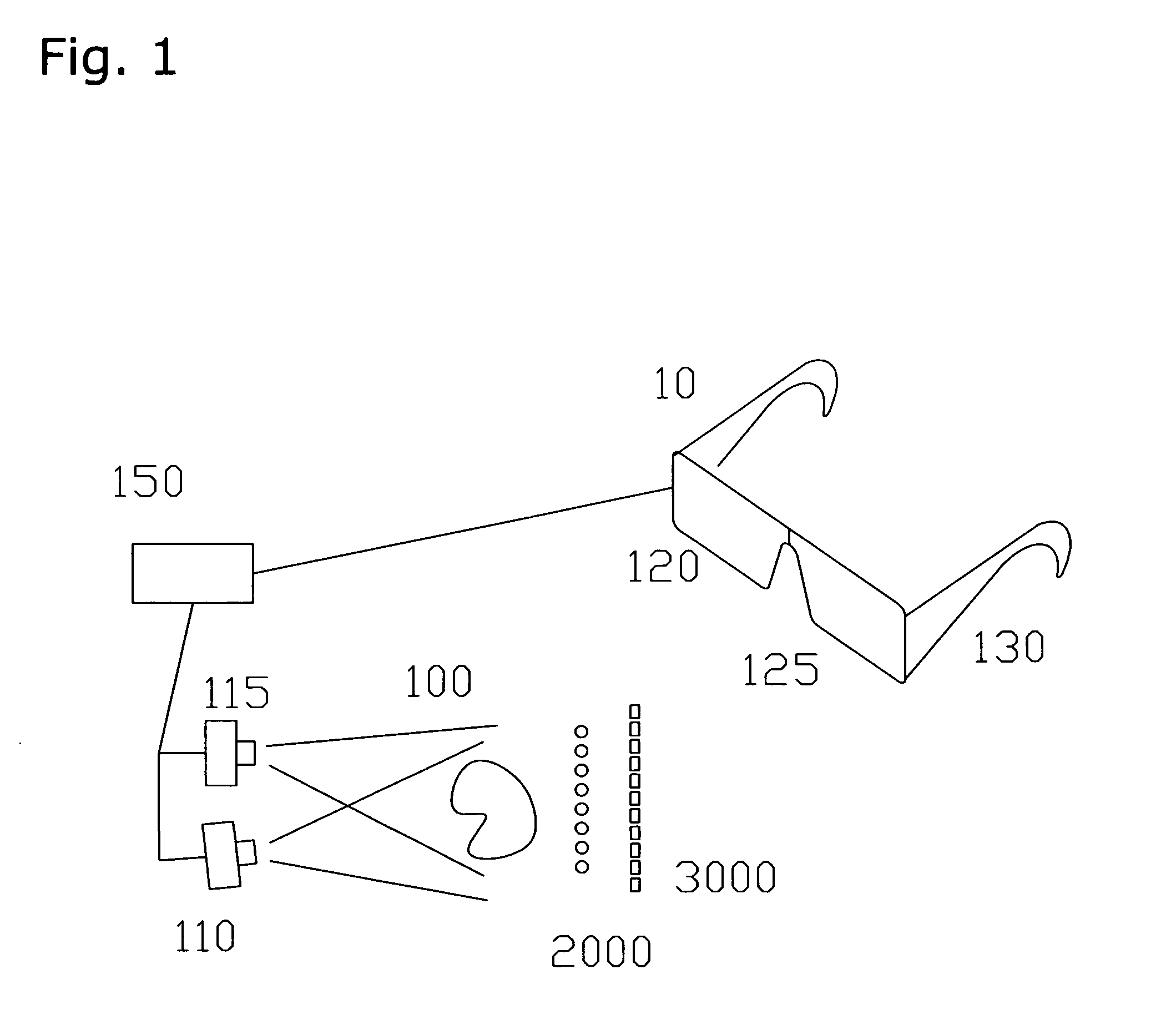
[0060]The general inventive concept in this application relates to improved methods and constructions to achieve a complex visual display environment which includes dynamic and precise focal length for each pixel of each frame of a visual display and the ability to present comfortable, three-dimensional image, virtual or augmented, to a single or multiple observers. This goal is ongoing quest for visual display engineers which has not been successfully addressed by the singular, or global methodologies of the prior art.

[0061]The present application discloses related inventive embodiments which lends themselves to incorporation in an array, including a preferred embodiment where the 2D array—which in the prior art would be orthogonal to the principal optical axis presenting the horizontal and vertical (X-Y) pixels—is turned approximately 90 degrees about the vertical axis (Y-Z) and aligned generally co-axially with the principal optical axis. In this embodiment, the array presents th...


PUM


Abstract

The present invention discloses an improved method and device for the immersive display of three-dimensional images with visual accommodation. An improved method for manufacturing a visual display incorporating a scanned light source and an improved method of presenting visual information are disclosed. A complete, immersive display environment is also presented.

Description

TECHNICAL FIELD[0001]This invention relates generally to display devices and more particularly to 3D imaging displays devices having an optional variable visual image distance. This application incorporates by reference my related and earlier filed applications and disclosures, and claims the continuation-in-part benefit of Ser. No. 11 / 149,638, which is a CIP of Ser. No. 10 / 207,620; which is a CIP of Ser. Nos. 10 / 941,461 and 10 / 172,629; which are CIP of Ser. No. 9 / 706,260, which is a CIP of Ser. No. 8 / 074,398; which is a CIP of Ser. No. 7 / 799,066 and benefits from the non-provisional application 60 / 584,351,BACKGROUND ART[0002]Planar displays such as CRTs, LCD panels, laser scan and projection screens are well-known. These displays present an image at a fixed focal length from the audience. The appearance of three-dimensionality is a visual effect created by perspective, shading and occlusion and motion parallax. Integral photographic displays and lenticular autostereoscopic displays...

Claims


Application Information

Patent Timeline
Patent Type & Authority Applications(United States)
IPC IPC(8): G03B21/14G02B27/22H04N13/363
CPCG02B26/105G06F3/013G02B27/017G02B27/0172G02B2027/0132G02B2027/014G02B2027/0178H04N13/0402H04N13/0404H04N13/0418H04N13/0422H04N13/044H04N13/0459H04N13/0497G02B26/12H04N13/302H04N13/305H04N13/32H04N13/344H04N13/324H04N13/363H04N13/398
Inventor SOLOMON, DENNIS J.
Owner SOLOMON DENNIS J
Why Eureka
Try Eureka