
Adapt-a-bowl

a technology of adaptable bows and bows, which is applied in the field of adaptable bows, can solve the problems of affecting the use of the device, so as to achieve the effect of convenient transportation, increased access, and easy transportation

Inactive Publication Date: 2011-01-13
STANISLAWSKI JOSEPH MATTHEW +1
View PDF12 Cites 0 Cited by
  • Summary
  • Abstract
  • Description
  • Claims
  • Application Information

AI Technical Summary

Benefits of technology

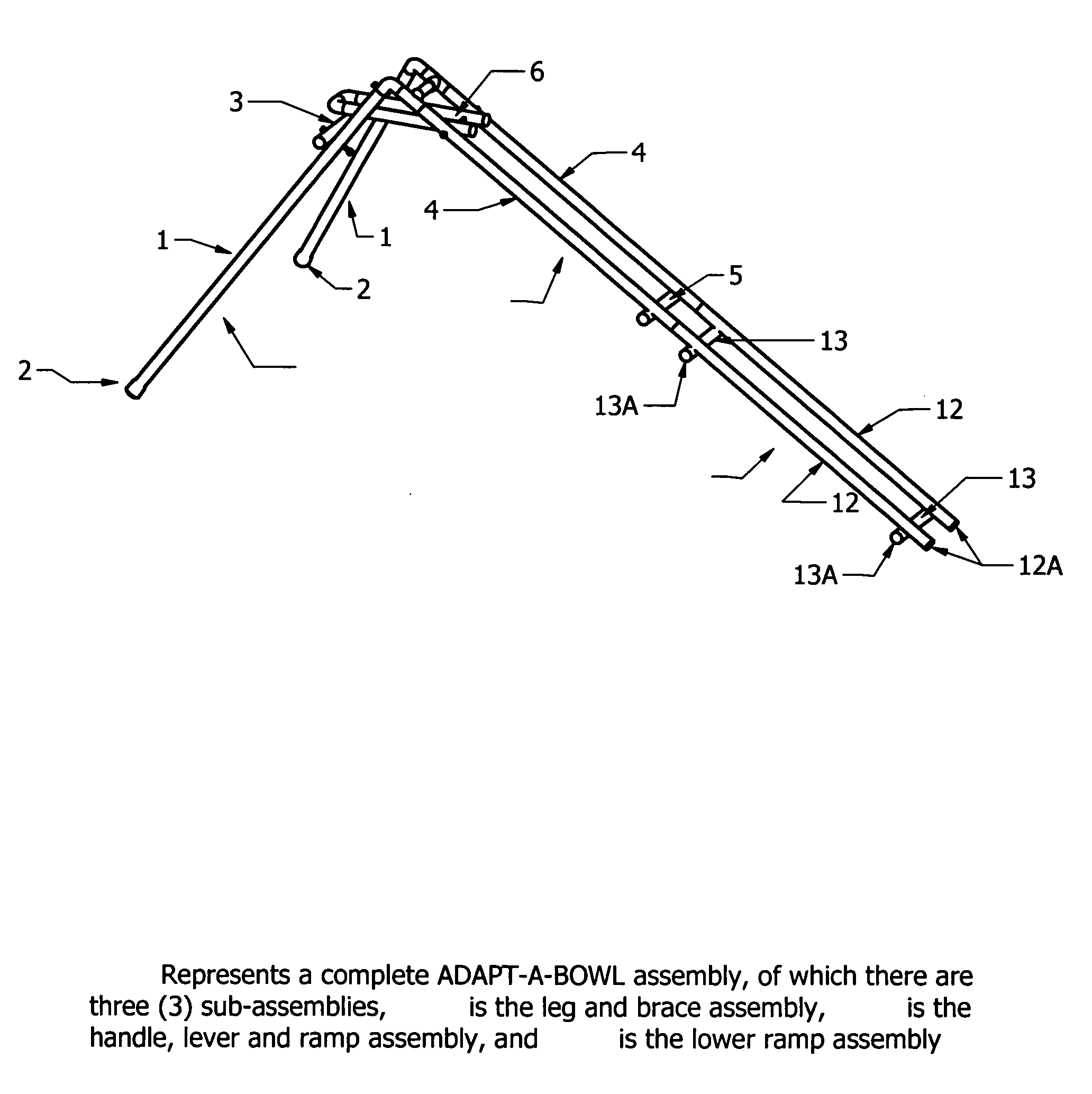
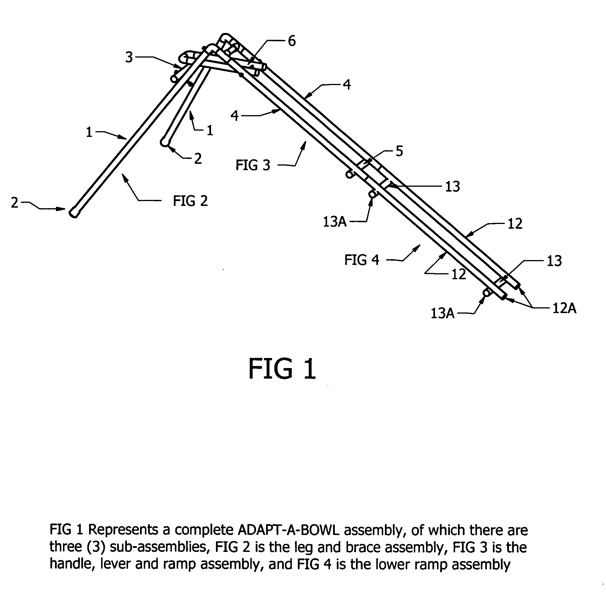
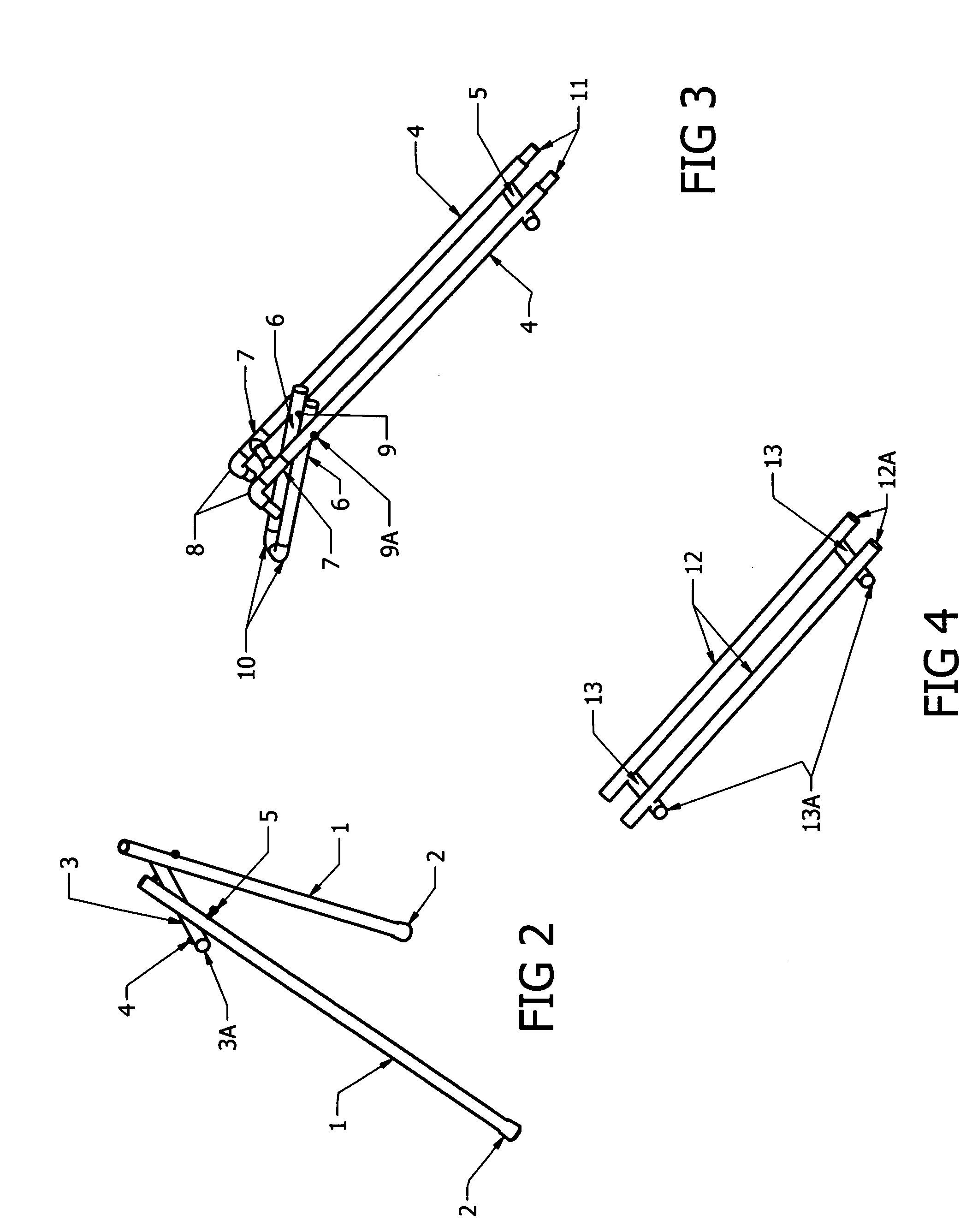
[0009]Another aspect of the Adapt-A-Bowl design is its capability to be a portable unit consisting of three main parts, FIG. 2 the leg subassembly, FIG. 3 the ball and ramp subassembly, and FIG. 4 the lower ramp subassembly. When all three subassemblies are combined they form FIG. 1, a complete Adapt-A-Bowl assembly ready to be used by an individual with moderate to severe physical disabilities. The Adapt-A-Bowl device is disassembled into the three subassemblies and is packed into a storage bag so that it can be easily transported from one school location to another.
[0010]The Adapt-A-Bowl is a lightweight and durable unit that is easily transported to various locations including but not limited to schools, hospitals, daycare centers, and homes. This ease of transport increases the access of individuals with severe disabilities who use wheelchairs and gait trainers to participate in a variety of sporting activities. It is preferred that this device be used with individuals who have difficulty manipulating their arms, hands, legs or other extremities similarly to their peers so that they can enjoyably participate in various sports alongside their peers.

Problems solved by technology

These individuals often have greater difficulty extending their arms or legs fully to push a bowling ball down a ramp or opening their hands completely to grasp, pull, and release a handle.
This pushing action may be quite difficult for a person with severe disabilities who does not possess the strength to control the weight of a bowling ball.
These prior art devices fail to accommodate those with severe disabilities who have a more limited range of motion.
Furthermore, all of these prior art devices appear to be constructed from tubular steel that may make it difficult for individuals with severe disabilities to adjust for accuracy in rolling the bowling ball down the ramp.

Method used


Image

  • Adapt-a-bowl
  • Adapt-a-bowl
  • Adapt-a-bowl

Examples


Embodiment Construction

[0016]In referring to the drawings, FIG. 1 represents the three subassemblies, FIG. 2 the leg and brace assembly, FIG. 3 the handle, lever, and ramp assembly, and FIG. 4 the lower ramp assembly, all of which are the subassemblies that make up the Adapt-A-Bowl portable rolling device. The lightweight construction of the Adapt-A-Bowl is made possible due to the use of ⅜″-1″ inside diameter (i.d.) PVC which is the main material for construction.

[0017]FIG. 2 consists of the leg portion 1 which has rubber tips 2 to help stabilize the leg assembly. A horizontal brace 3 has a protective insert 3A to hold together both legs 1. The legs 1 and the brace 3 are joined together with a bolt 4 going through both the legs 1 and brace 3 with a machine nut 5.

[0018]FIG. 3 consists of the ramp 4 held in place by the ramp brace 5 with joining dowel inserts 11. The ramp 4 also consists of the tee 7 with coupler to hold together the upper portion of the ramp 4. At the top of the tee 7 the 90° angle and in...


PUM


Abstract

The Adapt-A-Bowl is a lightweight and durable device that is easily transported to various locations including but not limited to schools, hospitals, daycare centers, and homes. This ease of transport increases the access of individuals with moderate to severe disabilities who use wheelchairs and gait trainers to participate in a variety of sporting activities. The supportive legs creating the angle of descent are collapsible and fit into the upper handle, lever and ramp assembly. The upper lever and ramp assembly are designed to house a lightweight ball which is set on a lever system and activated by the handle. The lower ramp assembly finalizes the length of the ramp to send the ball down the ramp. The key advantage to this device is its portability and three-piece assembly which all fit into a carrying bag.

Description

CROSS REFERENCE TO RELATED APPLICATIONS[0001]Not applicableSTATEMENT REGARDING FEDERALLY SPONSORED RESEARCH OR DEVELOPMENT[0002]Not applicableBACKGROUND OF THE INVENTION[0003]1. Field of the Invention[0004]The ADAPT-A-BOWL device is designed to be used by handicapped students of all ages anywhere in a school environment who use or rely on a wheelchair or gate trainer. The ADAPT-A-BOWL is designed as a three-piece unit so teachers can assemble and disassemble it in a matter of minutes. A lightweight ball is released by a lever handle which projects the ball down the ramp to knock down plastic bowling pins. The three-piece design helps the special education teacher to pack the unit into a storage bag and move from one school location to another.[0005]2. Description of Prior Art[0006]As seen with the following patents, U.S. Pat. Nos. 6,042,482; 6,227,981 B1; 3,159,401, all of the prior art devices are intended to use for bowlers with mild to moderate physical disabilities. They do not ...

Claims


Application Information

Patent Timeline
Patent Type & Authority Applications(United States)
IPC IPC(8): A63D5/00
CPCA63D5/00A63D3/02
Inventor STANISLAWSKI, JOSEPH MATTHEWSTANISLAWSKI, ADAM JOSEPH
Owner STANISLAWSKI JOSEPH MATTHEW
Learn More