Apparatus for thermal-slide debonding of temporary bonded semiconductor wafers

a technology of temporary bonded and bonded semiconductors, which is applied in the direction of mechanical apparatus, other domestic objects, manufacturing tools, etc., can solve the problems of increasing difficulty in mechanical holding of wafers and maintaining control of planarity and integrity

Inactive Publication Date: 2011-01-20
SUSS MICRO TEC LITHOGRAPHY
View PDF23 Cites 27 Cited by
  • Summary
  • Abstract
  • Description
  • Claims
  • Application Information

AI Technical Summary

Problems solved by technology

However, for wafer thicknesses of less than 200 micrometer and especially for wafers of less than 100 micrometers, it becomes increasingly difficult to mechanically hold the wafers and to maintain control of the planarity and integrity of the wafers during thinning.

Method used


Image

  • Apparatus for thermal-slide debonding of temporary bonded semiconductor wafers
  • Apparatus for thermal-slide debonding of temporary bonded semiconductor wafers
  • Apparatus for thermal-slide debonding of temporary bonded semiconductor wafers

Examples


Embodiment Construction

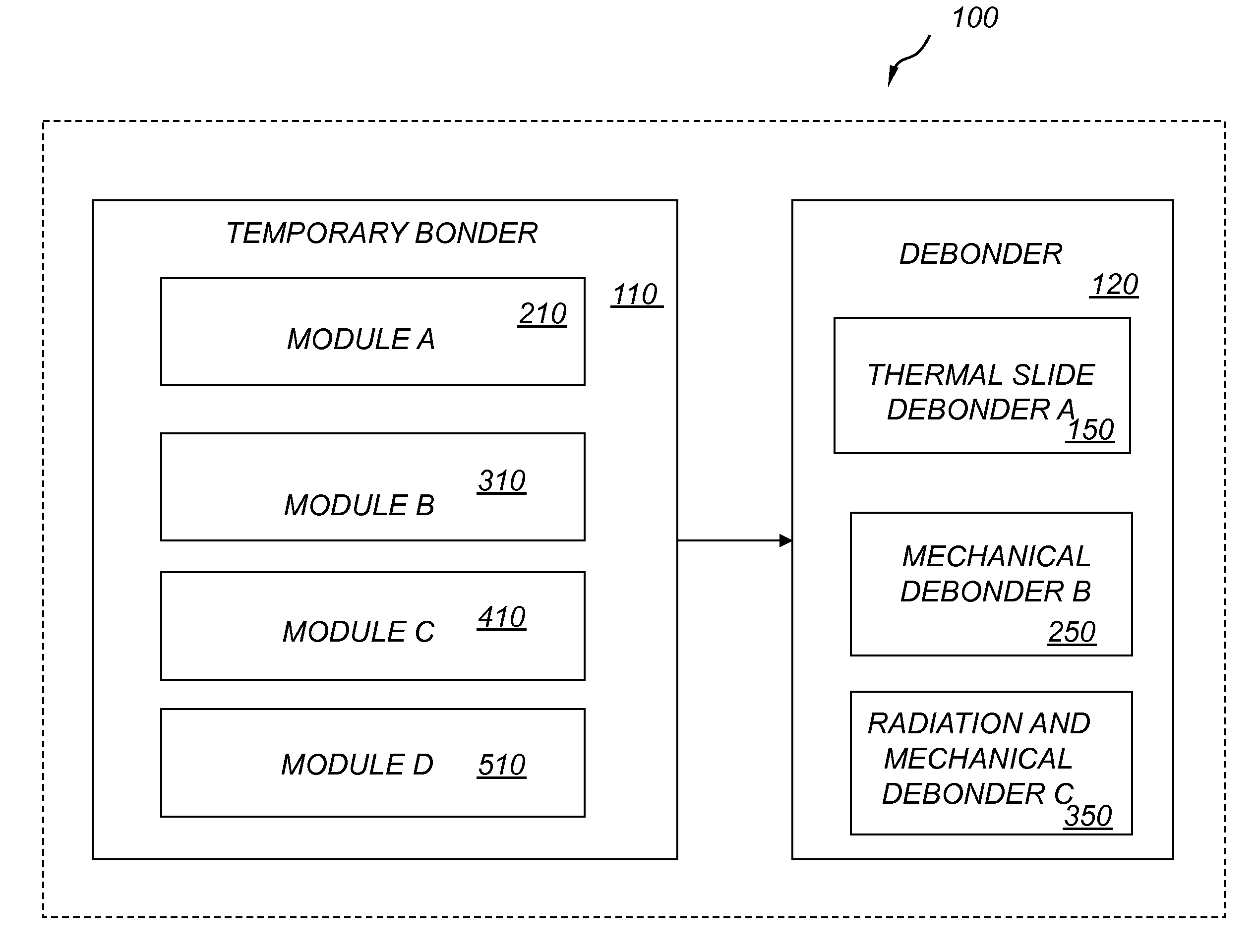
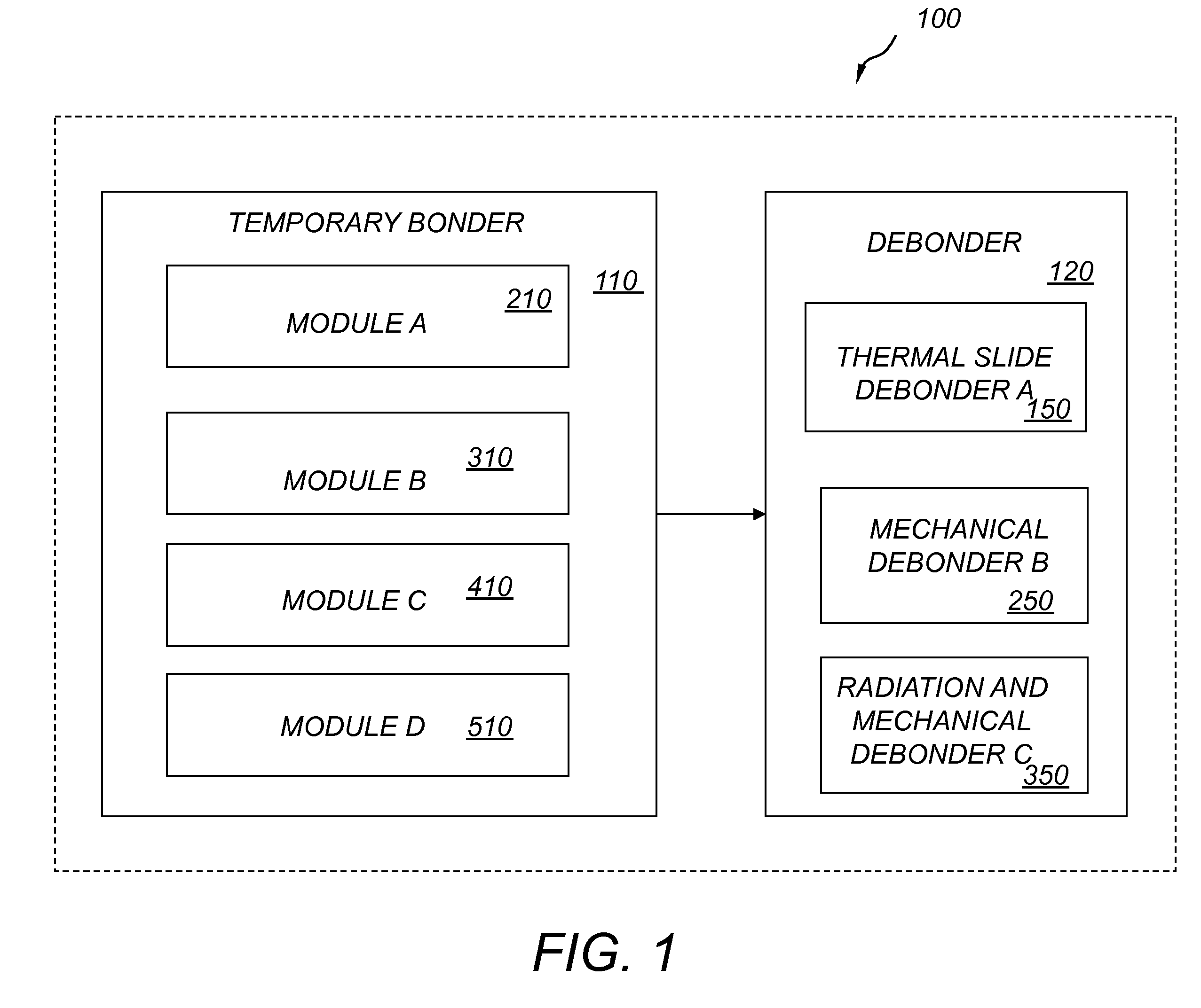
[0050]Referring to FIG. 1, an improved apparatus for temporary wafer bonding and debonding 100 includes a temporary bonder cluster 110 and a debonder cluster 120. The temporary bonder cluster 110 includes temporary bonder module A, module B, module C, and module D, 210, 310, 410 and 510 respectively. Debonder cluster 120 includes a thermal slide debonder A 150, a mechanical debonder B 250 and a radiation / mechanical debonder C 350. Bonder cluster 110 facilitates the temporary bonding processes A, B, C, and D, 60a, 70a, 80a and 90a, shown in FIG. 1A, FIG. 2A, FIG. 3A, and FIG. 4, respectively, among others. Debonder cluster 120 facilitates the debonding processes A, B and C, 60b, 70b, and 80b, shown in FIG. 1A, FIG. 2A and FIG. 3A, respectively.

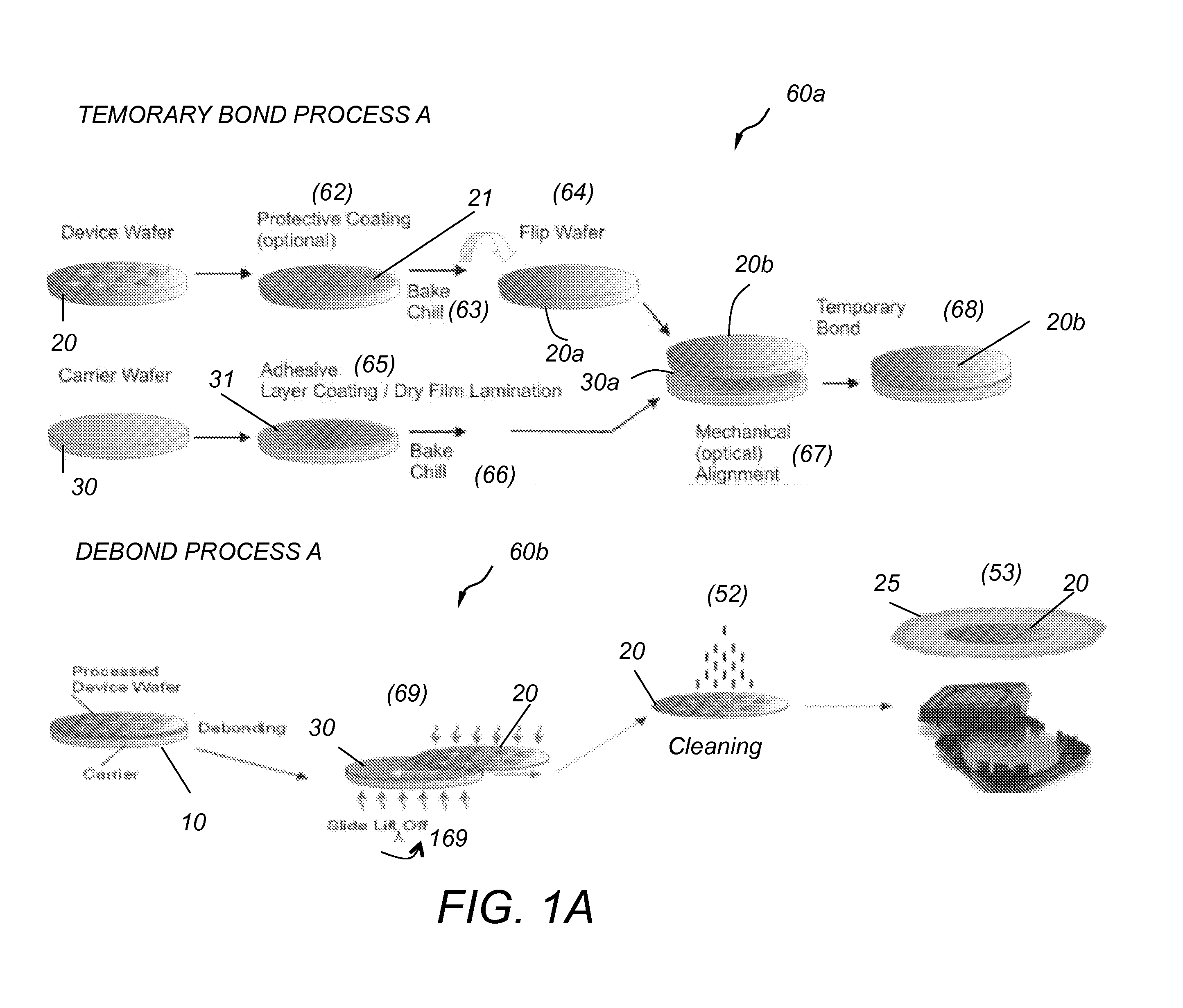
[0051]Referring to FIG. 1A, temporary bond process A 60a includes the following steps. First, device wafer 20 is coated with a protective coating 21 (62), the coating is then baked and chilled (63) and then the wafer is flipped (64). A carrier ...


PUM

PropertyMeasurementUnit
diameteraaaaaaaaaa
diameteraaaaaaaaaa
thicknessaaaaaaaaaa

Abstract

A debonder apparatus for debonding two via an adhesive layer temporary bonded wafers includes a top chuck assembly, a bottom chuck assembly, a static gantry supporting the top chuck assembly, an X-axis carriage drive supporting the bottom chuck assembly, and an X-axis drive control. The top chuck assembly includes a heater and a wafer holder. The X-axis drive control drives horizontally the bottom chuck assembly from a loading zone to a process zone under the top chuck assembly and from the process zone back to the loading zone. A wafer pair comprising a carrier wafer bonded to a device wafer via an adhesive layer is placed upon the bottom chuck assembly at the loading zone oriented so that the unbonded surface of the device wafer is in contact with the bottom assembly and is carried by the X-axis carriage drive to the process zone under the top chuck assembly and the unbonded surface of the carrier wafer is placed in contact with the top chuck assembly. The X-axis drive control initiates horizontal motion of the X-axis carriage drive along the X-axis while heat is applied to the carrier wafer via the heater and while the carrier wafer is held by the top chuck assembly via the wafer holder and thereby causes the device wafer to separate and slide away from the carrier wafer.

Description

CROSS REFERENCE TO RELATED CO-PENDING APPLICATIONS[0001]This application claims the benefit of U.S. provisional application Ser. No. 61 / 169,753 filed Apr. 16, 2009 and entitled “IMPROVED APPARATUS FOR TEMPORARY WAFER BONDING”, the contents of which are expressly incorporated herein by reference.FIELD OF THE INVENTION[0002]The present invention relates to an apparatus for thermal-slide debonding of temporary bonded semiconductor wafers, and more particularly to an industrial-scale thermal-slide debonder for debonding semiconductor wafers bonded via an adhesive.BACKGROUND OF THE INVENTION[0003]Several semiconductor wafer processes include wafer thinning steps. In some applications the wafers are thinned down to a thickness of less than 100 micrometers for the fabrication of integrated circuit (IC) devices. Thin wafers have the advantages of improved heat removal and better electrical operation of the fabricated IC devices. In one example, GaAs wafers are thinned down to 25 micrometers...

Claims


Application Information

Patent Timeline
Patent Type & Authority Applications(United States)
IPC IPC(8): B23P19/00
CPCB32B38/1858Y10T156/1168B32B2309/105B32B2457/14H01L21/67092H01L21/67132H01L21/6835H01L2221/68327Y10S156/93Y10S156/941H01L21/673H01L2221/68318Y10S156/932Y10S156/942Y10S156/943Y10T279/26Y10T29/53274Y10T279/29Y10T279/21Y10T156/1153Y10T156/1972Y10T156/1911Y10T156/1132Y10T156/1978Y10T279/18Y10T156/1189Y10T156/1944Y10T29/49817Y10T156/1158Y10T156/1917B32B43/006H01L21/02H01L21/20H01L21/68
Inventor GEORGE, GREGORYJOHNSON, HALEGORUN, PATRICKHUGHLETT, EMMETTHERMANOWSKI, JAMESSTILES, MATTHEW
Owner SUSS MICRO TEC LITHOGRAPHY
Why Eureka
Try Eureka