
Methods and apparatus for hazard control

a hazard control and method technology, applied in fire rescue, medical science, dental surgery, etc., can solve the problems of complex and require significant installation time and cost, and system may be susceptible to failur

Active Publication Date: 2011-01-20
FIRETRACE USA LLC
View PDF3 Cites 11 Cited by
  • Summary
  • Abstract
  • Description
  • Claims
  • Application Information

AI Technical Summary

Benefits of technology

The system effectively and efficiently delivers control materials to hazardous areas, reducing installation complexity and enhancing reliability by using a pressure tube that degrades in response to heat to generate a pneumatic signal for automatic extinguishant deployment.

Problems solved by technology

Such systems, however, are complex and require significant installation time and cost.
In addition, such systems may be susceptible to failure in the event of malfunction or loss of power.

Method used


Image

  • Methods and apparatus for hazard control
  • Methods and apparatus for hazard control
  • Methods and apparatus for hazard control

Examples


Embodiment Construction

[0010]The present invention may be described in terms of functional block components and various processing steps. Such functional blocks may be realized by any number of hardware or software components configured to perform the specified functions and achieve the various results. For example, the present invention may employ various vessels, sensors, detectors, control materials, valves, and the like, which may carry out a variety of functions. In addition, the present invention may be practiced in conjunction with any number of hazards, and the system described is merely one exemplary application for the invention. Further, the present invention may employ any number of conventional techniques for delivering control materials, sensing hazard conditions, controlling valves, and the like.

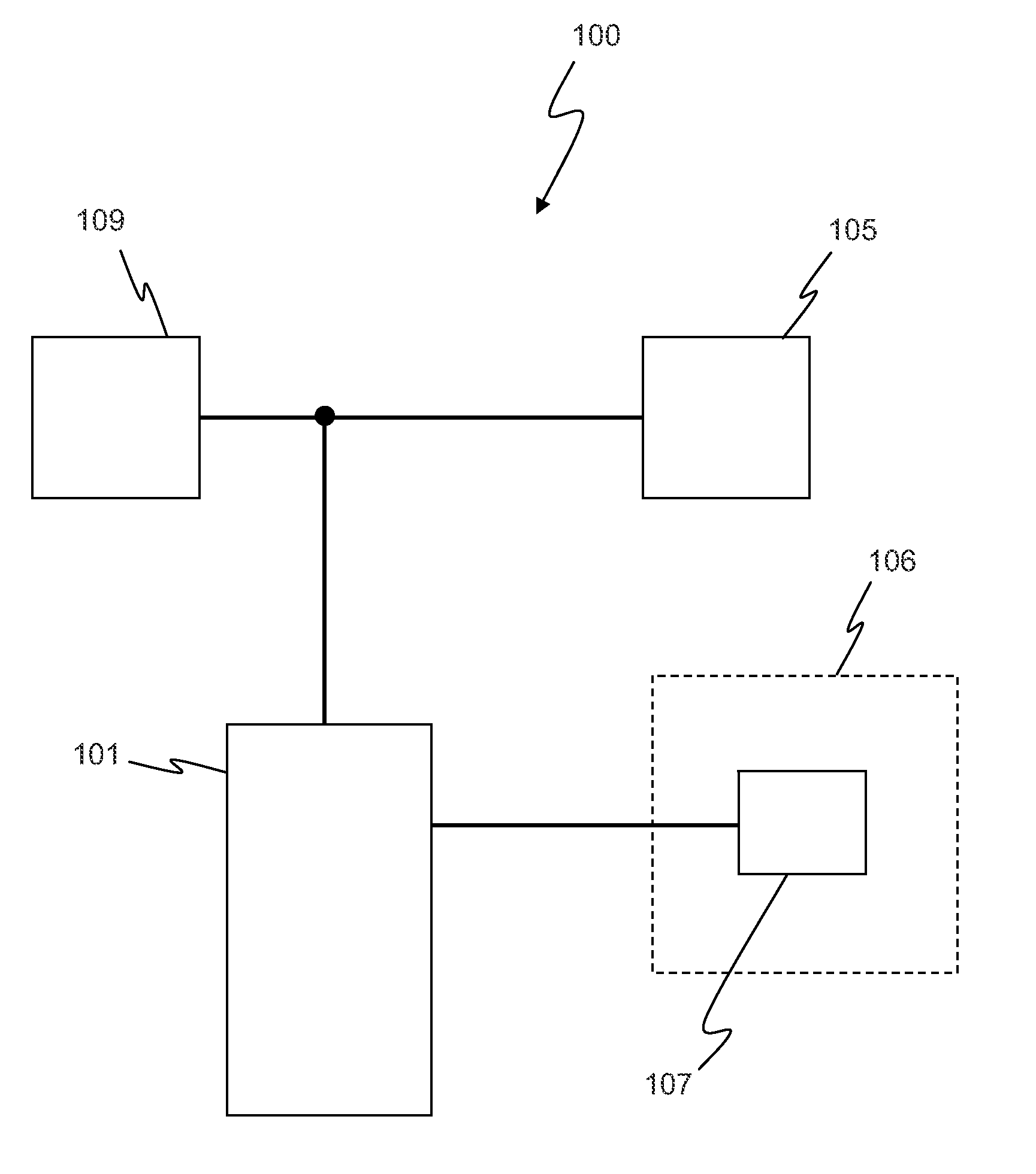
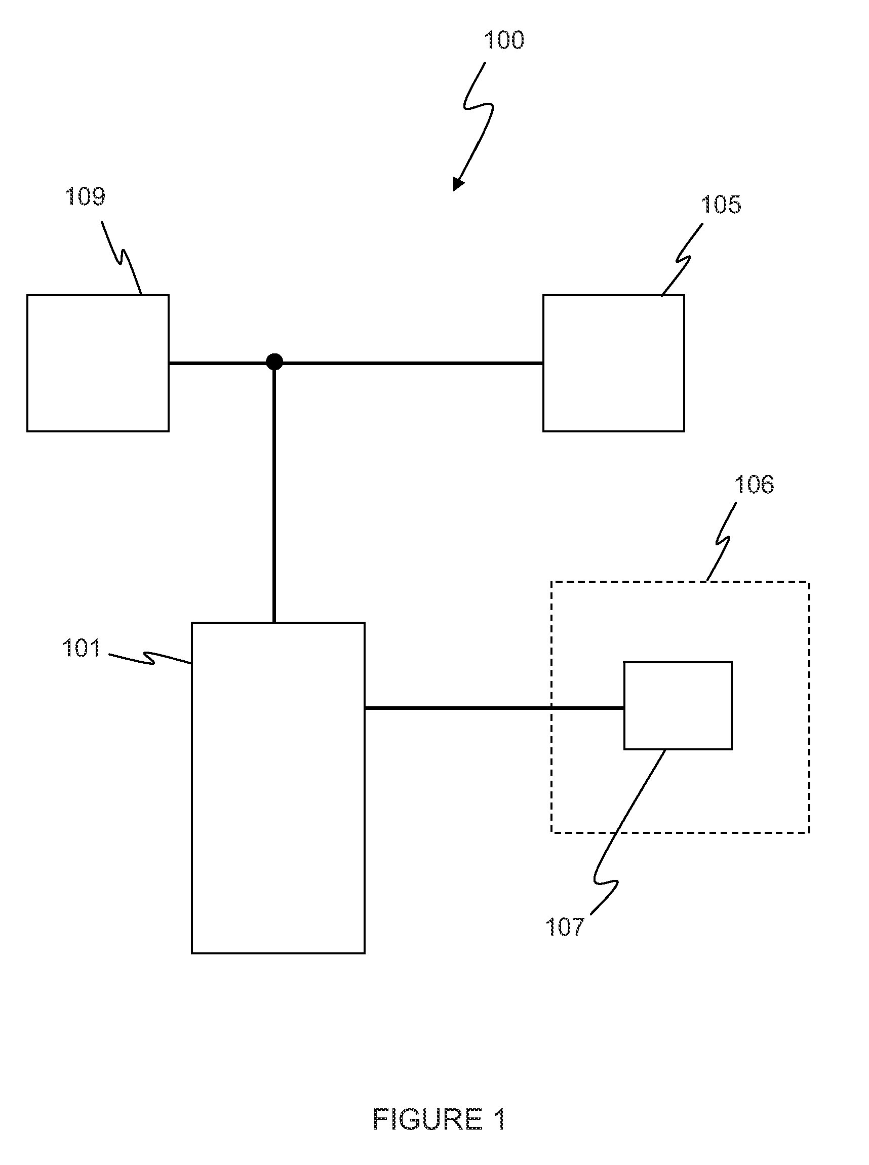
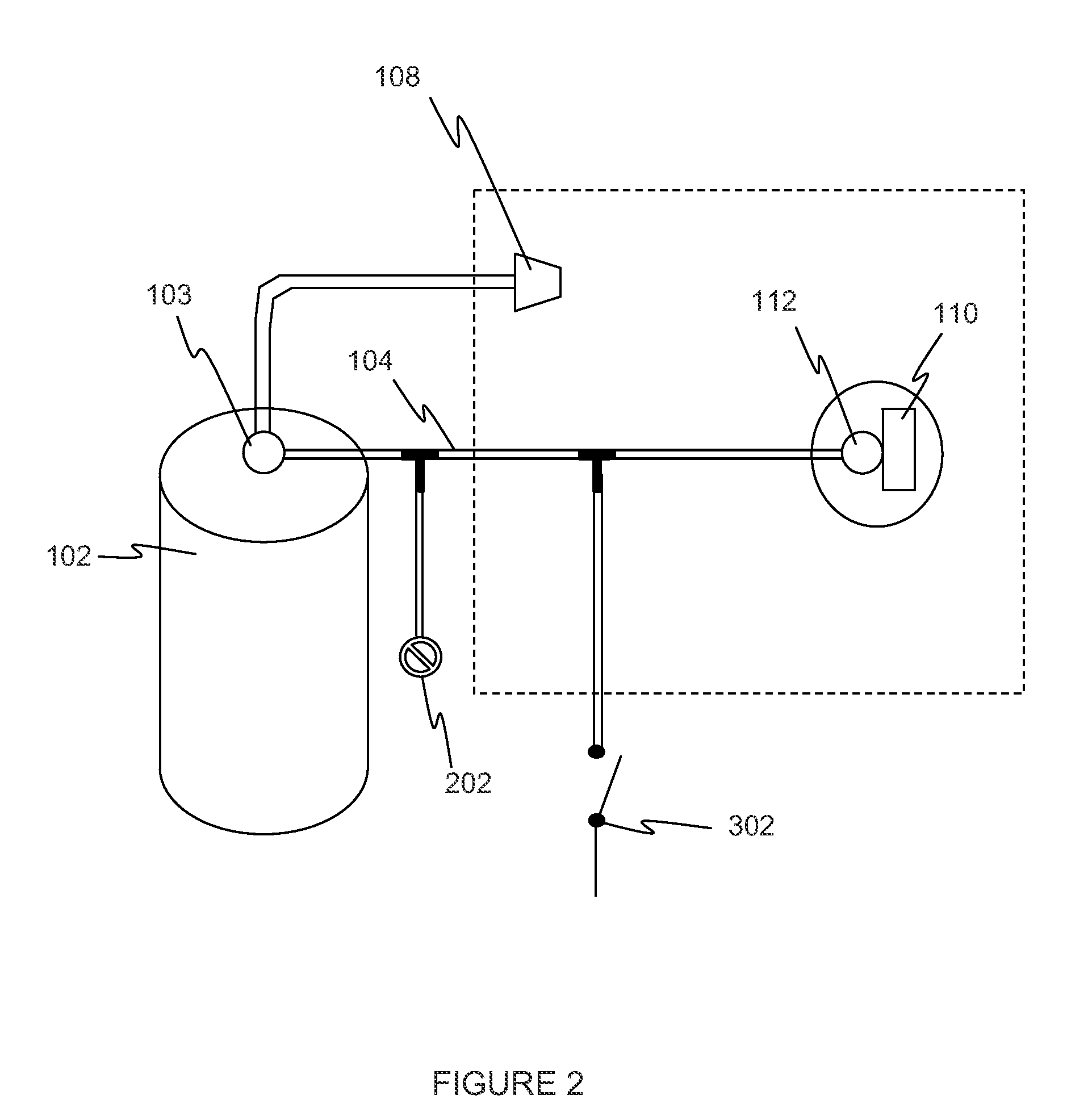
[0011]Referring now to FIGS. 1 and 2, a hazard control system 100 for controlling a hazard according to various aspects of the present invention may comprise a control material source 101 for provid...


PUM


Abstract

A hazard control system according to various aspects of the present invention is configured to deliver a control material in response to detection of a hazard. In one embodiment, the hazard control system comprises a pressure tube having an internal pressure and configured to leak in response to exposure to heat. The leak changes the internal pressure and generates a pneumatic signal. A fire detector may also detect a fire condition associated with fire. A valve may be coupled to the fire detector and the pressure tube. The valve is configured to change the internal pressure and generate the pneumatic signal in response to a signal from the fire detector. The pneumatic signal triggers a delivery system to deliver the control material.

Description

CROSS-REFERENCES TO RELATED APPLICATIONS[0001]This application is a continuation of U.S. patent application Ser. No. 12 / 172,148, filed on Jul. 11, 2008, which claims the benefit of U.S. Provisional Patent Application No. 60 / 949,586, filed on Jul. 13, 2007, and incorporates the disclosure of each application in its entirety by reference. To the extent that the present disclosure conflicts with any referenced application, however, the present disclosure is to be given priority.BACKGROUND OF THE INVENTION[0002]Hazard control systems often comprise a smoke detector, a control board, and an extinguishing system. When the smoke detector detects smoke, it sends a signal to the control board. The control board then typically sounds an alarm and triggers the extinguishing system in the area monitored by the smoke detector. Such systems, however, are complex and require significant installation time and cost. In addition, such systems may be susceptible to failure in the event of malfunction ...

Claims


Application Information

Patent Timeline
Patent Type & Authority Applications(United States)
IPC IPC(8): A62C2/00A62C37/36
CPCY10T29/49826A62C37/44
Inventor ECKHOLM, WILLIAM A.SEEBALUCK, LEN
Owner FIRETRACE USA LLC
Learn More