Motor driven surgical fastener device with mechanisms for adjusting a tissue gap within the end effector

a surgical and end effector technology, applied in the field of surgical staplers, can solve the problems of incomplete firing, ineffective forming of closed staples in severed tissue, and tissue severing and stapling

Active Publication Date: 2011-01-20
CILAG GMBH INT
View PDF80 Cites 311 Cited by
  • Summary
  • Abstract
  • Description
  • Claims
  • Application Information

AI Technical Summary

Benefits of technology

[0010]In one general aspect, the present invention is directed to a motorized surgical cutting and fastening instrument that provides feedback to the user regarding the position, force and / or deployment of the end effector. The instrument, in various embodiments, also allows the operator to control the end effector, including being able to stop deployment if so desired. The instrument may include two triggers in its handle—a closure trigger and a firing trigger—with separate actuation motions. When an operator of the instrument retracts the closure trigger, tissue positioned in the end effector may be clamped by the end effector. Then, when the operator retracts the firing trigger, a motor may power, via a gear drive train, a rotational main drive shaft assembly, which causes a cutting instrument in the end effector to sever the clamped tissue.

Problems solved by technology

Firing the surgical stapler causes severing and stapling the tissue.
Otherwise, opposing jaws may be drawn too close together, especially pinching at their distal ends, and thus not effectively forming closed staples in the severed tissue.
At the other extreme, an excessive amount of clamped tissue may cause binding and an incomplete firing.
Endoscopic staplers / cutters continue to increase in complexity and function with each generation.
These devices have not faired much better than traditional hand-powered devices, but for a different reason.
These user-feedback effects are not suitably realizable in present motor-driven endocutters.
As a result, there is a general lack of acceptance by physicians of motor-drive endocutters where the cutting / stapling operation is actuated by merely pressing a button.

Method used


Image

  • Motor driven surgical fastener device with mechanisms for adjusting a tissue gap within the end effector
  • Motor driven surgical fastener device with mechanisms for adjusting a tissue gap within the end effector
  • Motor driven surgical fastener device with mechanisms for adjusting a tissue gap within the end effector

Examples


Embodiment Construction

[0044]The owner of the subject application also owns the following U.S. Patent Applications that were filed on even date herewith and which are each herein incorporated by reference in their respective entirety:

[0045]U.S. Patent Application entitled “Motor Driven Surgical Fastener Device With Cutting Member Reversing Mechanism”, Attorney Docket No. END6549USCIP1 / 100280CIP1; and

[0046]U.S. Patent Application entitled “Motor Driven Surgical Fastener Device With Cutting Member Lockout Arrangements, Attorney Docket No. END6547USCIP1 / 100270CIP1.

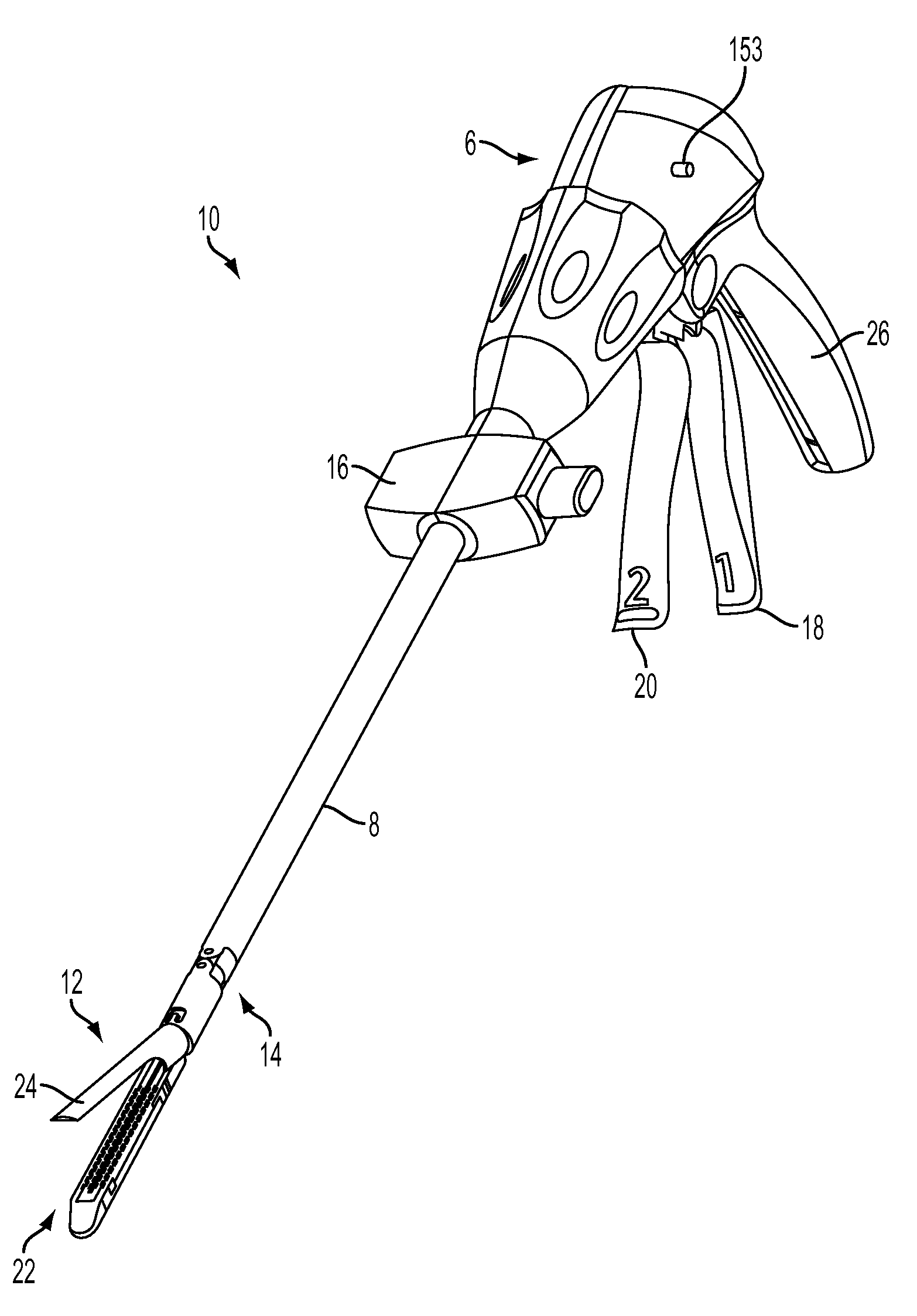
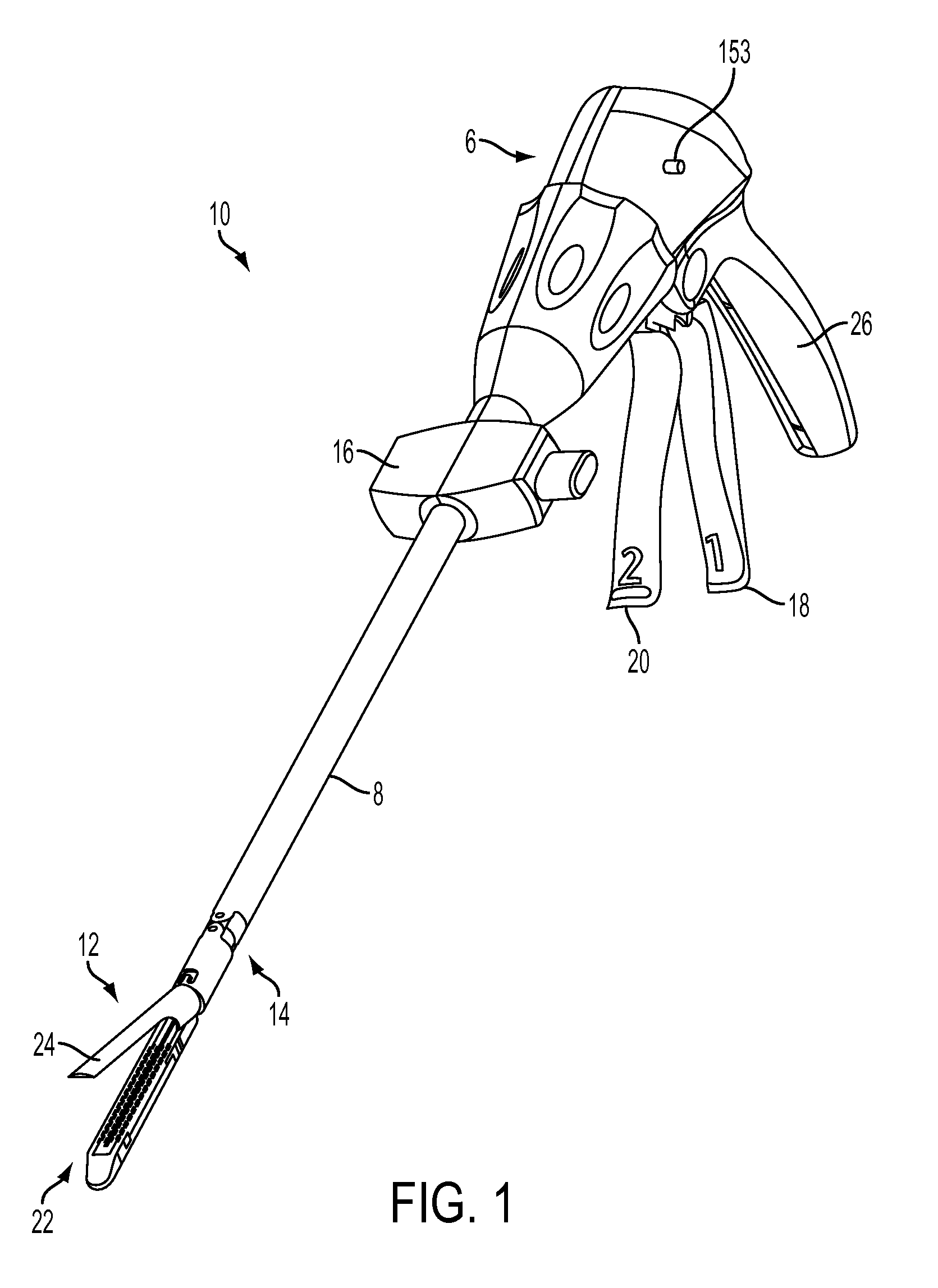
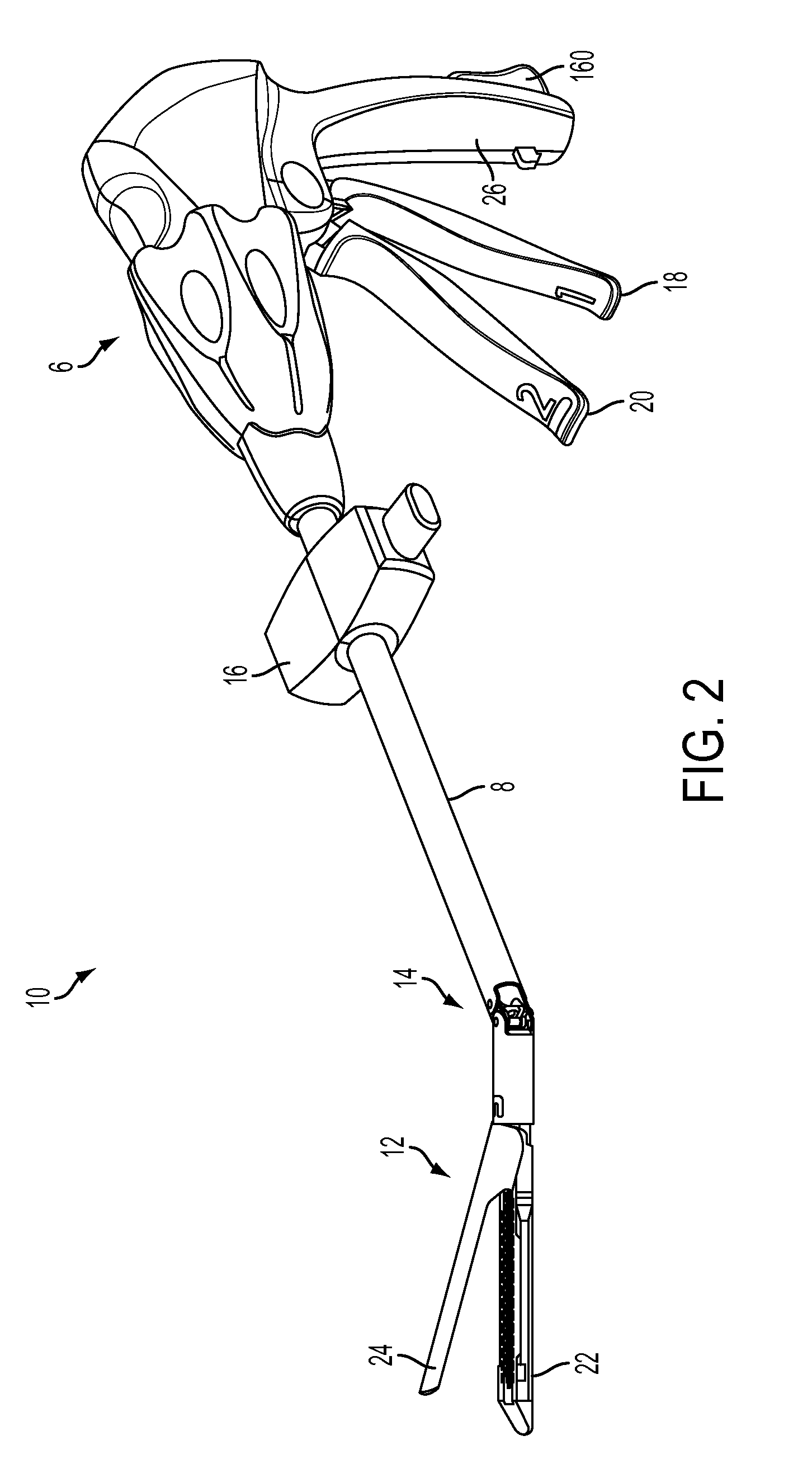
[0047]Certain exemplary embodiments will now be described to provide an overall understanding of the principles of the structure, function, manufacture, and use of the devices and methods disclosed herein. One or more examples of these embodiments are illustrated in the accompanying drawings. Those of ordinary skill in the art will understand that the devices and methods specifically described herein and illustrated in the accompanying drawings are...


PUM

PropertyMeasurementUnit
rotationaaaaaaaaaa
electricallyaaaaaaaaaa
thicknessaaaaaaaaaa

Abstract

A surgical fastener apparatus having a handle, an elongated shaft having a proximal end attached to the handle and a distal end extending therefrom. An end effector including a pair of jaws pivoted at a proximal end thereof and movable between an open and closed position. A cartridge containing a plurality of surgical fasteners, the cartridge attached to the end effector. An electrically powered actuator for deploying the surgical fasteners, the actuator including a power source and a motor. Means for electrically adjusting the amount of spacing between the jaws when the end effector is in the closed position.

Description

CROSS REFERENCE TO RELATED APPLICATIONS[0001]This non-provisional application is a continuation-in-part application of U.S. patent application Ser. No. 12 / 693,461, entitled “Driven Surgical Stapler Improvements”, to Frederick E. Shelton, IV, filed on Jan. 26, 2010, which claims the benefit of U.S. Provisional Application Ser. No. 61 / 150,387 entitled “Motor-Driven Surgical Stapler Improvements” to Frederick E. Shelton, IV filed on Feb. 6, 2009, the entire disclosures of each being herein incorporated by reference in their respective entireties.BACKGROUND[0002]An example of a surgical stapler suitable for endoscopic applications is described in U.S. Pat. No. 5,465,895, which is hereby incorporated herein by reference in its entirety. Such device comprises an endocutter that has distinct closing and firing actions. Another example of a motor driven surgical stapler is disclosed U.S. Patent Application Publication No. US 2007 / 0175958 A1, entitled “Motor-Driven Surgical Cutting and Faste...

Claims


Application Information

Patent Timeline
Patent Type & Authority Applications(United States)
IPC IPC(8): A61B17/068
CPCA61B17/07207A61B2017/00017A61B2017/00398A61B2017/00734A61B17/068A61B2017/2923A61B2017/2927A61B2017/320052A61B2017/0725
Inventor SHELTON, IV, FREDERICK E.
Owner CILAG GMBH INT
Why Eureka
Try Eureka