Apparatus with a seal

a technology of seals and apparatuses, applied in the direction of engine seals, gear lubrication/cooling, shafts and bearings, etc., can solve the problems of lubricant leakage from the interior of the apparatus, the oil seal deteriorates after long-term use, etc., and achieve the effect of preventing the degradation of the sealing performance of secondary oil seals

Inactive Publication Date: 2011-01-20
NABLESCO CORP
View PDF16 Cites 9 Cited by
  • Summary
  • Abstract
  • Description
  • Claims
  • Application Information

AI Technical Summary

Benefits of technology

[0016]According to the apparatus with a seal taught in the present specification, when the secondary oil seal is moved to the sealing position, foreign material can be prevented from being trapped between the secondary oil seal and the first member, or between the secondary oil seal and the second member. Degradation of the sealing performance of the secondary oil seal can be prevented.

Problems solved by technology

Since the oil seal constantly contacts the shaft, the oil seal deteriorates after long term use.
When the oil seal deteriorates, there is a possibility that the lubricant will leak from the interior of the apparatus.

Method used


Image

  • Apparatus with a seal
  • Apparatus with a seal
  • Apparatus with a seal

Examples


first embodiment

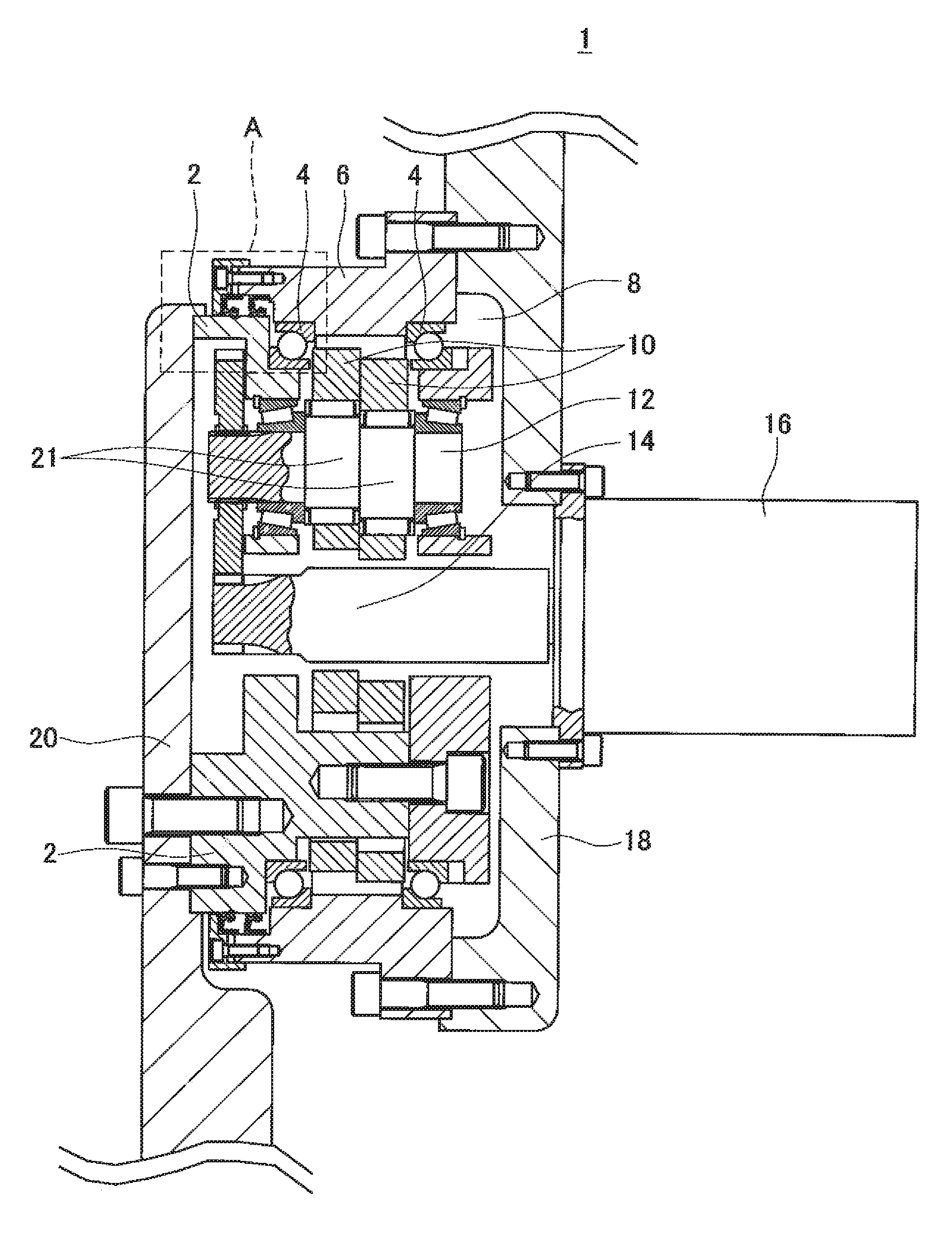
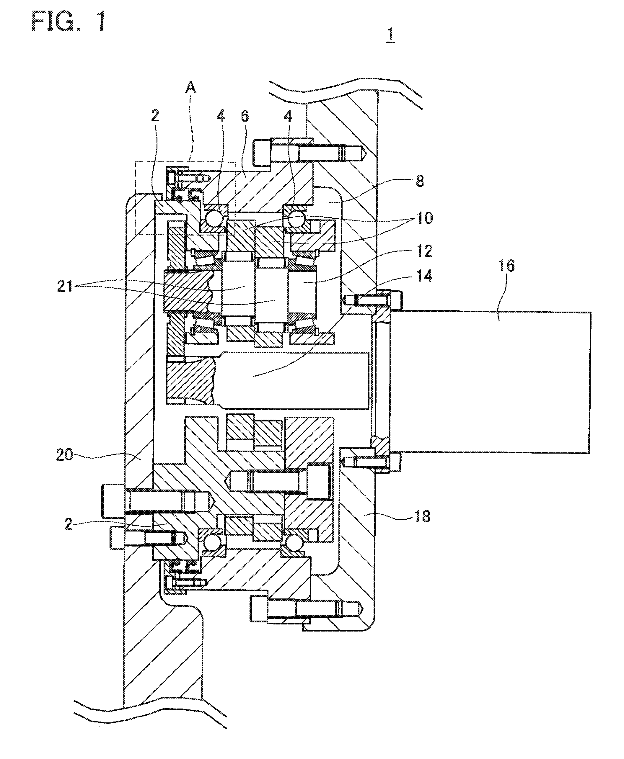
[0031]FIG. 1 shows a cross-sectional view of an essential part of a gear transmission 1 of the present embodiment. FIG. 2 shows an enlarged view of the region encompassed by dashed line A of FIG. 1. Moreover, in order to clarify the figures, cross-hatching is omitted from some components. The gear transmission 1 will first be described in a summary manner. The gear transmission 1 is an eccentric oscillating-type speed reducer and its basic configuration is well known. Consequently, the basic configuration of the gear transmission 1 will be briefly described.

[0032]The gear transmission 1 comprises a carrier 2 and a case 6. The case 6 is equivalent to a first member and the carrier 2 is equivalent to a second member. The carrier 2 is rotatably supported on the case 6 via a pair of angular ball bearings 4. The carrier 2 and the case 6 rotate relative to one another and lubricant is sealed between the two. As will be described later, a groove that encircles the circumferential direction...

second embodiment

[0049]Gear transmission 101 of the present embodiment will be described with reference to FIGS. 5 to 7. The gear transmission 101 of the present embodiment differs from the gear transmission 1 of the first embodiment only in the region encompassed by dashed line A (see FIG. 1). Consequently, in FIGS. 5 to 7, only the region corresponding to dashed line A of the gear transmission 1 is shown. Further, the same reference number or a reference number having the same two lower digits may be applied to a component that is in common with that of the above-described gear transmission 1, and an explanation thereof may be omitted.

[0050]As shown in FIG. 5, when the secondary oil seal 24 is positioned at the reserve position (the position where the inner circumferential surface of the secondary oil seal 24 opposes groove 138), the second dust seal 22 is positioned on the opposite side of the lubricant enclosure space 8 and the groove 138 is interposed therebetween. This is the same as with the ...

third embodiment

[0053]Gear transmission 201 will be described with reference to FIGS. 8 to 10. The gear transmission 201 differs from the gear transmission 1 of the first embodiment only in the region encompassed by dashed line A of FIG. 1. Consequently, in FIGS. 8 to 10, only the region corresponding to dashed line A of the gear transmission 1 is shown. Further, the same reference number or a reference number having the same two lower digits may be applied to a component that is in common with that of the above-described gear transmission 1, and an explanation thereof may be omitted.

[0054]In the gear transmission 201, a third dust seal 242 is attached to the support member 28 on the opposite side of the lubricant enclosure space 8 and the second sealing body 26 is interposed therebetween; the third dust seal 242 contacts the carrier 2. Therefore, the third dust seal 242 is not formed integrally with the secondary oil seal 24. Comparing the gear transmission 201 and the gear transmission 1, the wid...


PUM


Abstract

An apparatus comprises first and second members that are rotatable relative to each other. The second member is disposed in a circular hole defined in the first member. A main oil seal is disposed between the second member and an inner circumferential surface of the circular hole of the first member. A secondary oil seal is movable along a center line of the circular hole of the first member and is positioned on the opposite side of the main oil seal from the lubricant. A dust seal is positioned on the opposite side of the secondary oil seal from the lubricant. An annular groove is formed on one of the inner circumferential surface of the circular hole and an outer circumferential surface of the second member. The secondary oil seal is movable from a reserve position, which opposes the groove, to a sealing position, which does not oppose the groove.

Description

TECHNICAL FIELD[0001]The present application claims priority to Japanese Patent Application No. 2008-88583 filed on Mar. 28, 2008, the contents of which are hereby incorporated by reference into the present specification. The present invention relates to an apparatus with a seal that encloses a lubricant.BACKGROUND ART[0002]An apparatus, which seals a lubricant between two members that rotate relative to one another, is known. This apparatus comprises, e.g., a case having a circular hole, and a shaft passing through the circular hole. The shaft is positioned coaxially with a center line of the circular hole and rotates relative to the case. This type of apparatus encloses the lubricant within the case in order to rotate the shaft smoothly. That is, the lubricant is sealed between the two members (the case and the shaft) that rotate relative to one another. In case the shaft is exposed at the outside of the case, an oil seal is provided in a gap between the shaft and an inner circumf...

Claims


Application Information

Patent Timeline
Patent Type & Authority Applications(United States)
IPC IPC(8): F16H57/04F16J15/32F16C33/78
CPCF16J15/008
Inventor NAKAMURA, KOJI
Owner NABLESCO CORP
Why Eureka
Try Eureka