Power generating device

a power generation device and power technology, applied in the direction of generators/motors, mechanical equipment, machines/engines, etc., can solve the problems of inconvenient utilization, inconvenient utilization of external charging devices, and relatively difficult assembly of the process of external charging devices

Active Publication Date: 2011-01-20
SILICON TOUCH TECH INC
View PDF6 Cites 12 Cited by
  • Summary
  • Abstract
  • Description
  • Claims
  • Application Information

AI Technical Summary

Benefits of technology

[0020]In an embodiment of the present invention, the steering module includes a first gear module, a second gear module, a third gear module and a rotation shaft. The first gear module is meshed with the manual operating module, and the first gear module and the second gear module cover the rotation shaft. The second gear module is meshed with the third gear module, and the third gear module covers the one-way bearing. The manual operating module drives the second gear module to rotate through the first gear module, and the second gear module drives the one-way bearing and the rotating axle to rotate together through the third gear module, so that the rotating axle drives the rotor module to rotate. Since the second gear module and the third gear module have a high tooth ratio, rotation of the third gear module is accelerated.

Problems solved by technology

If the user stays outdoors for a long time, the rechargeable battery cannot be charged, which is inconvenient for utilization.
However, the external charging device is still inconvenient for utilization.
However, these two conventional power generating devices have relatively more components, so that assembling processes thereof are relatively difficult, and accordingly costs thereof cannot be reduced.

Method used


Image

  • Power generating device
  • Power generating device
  • Power generating device

Examples


Embodiment Construction

[0046]Reference will now be made in detail to the present preferred embodiments of the invention, examples of which are illustrated in the accompanying drawings. Wherever possible, the same reference numbers are used in the drawings and the description to refer to the same or like parts.

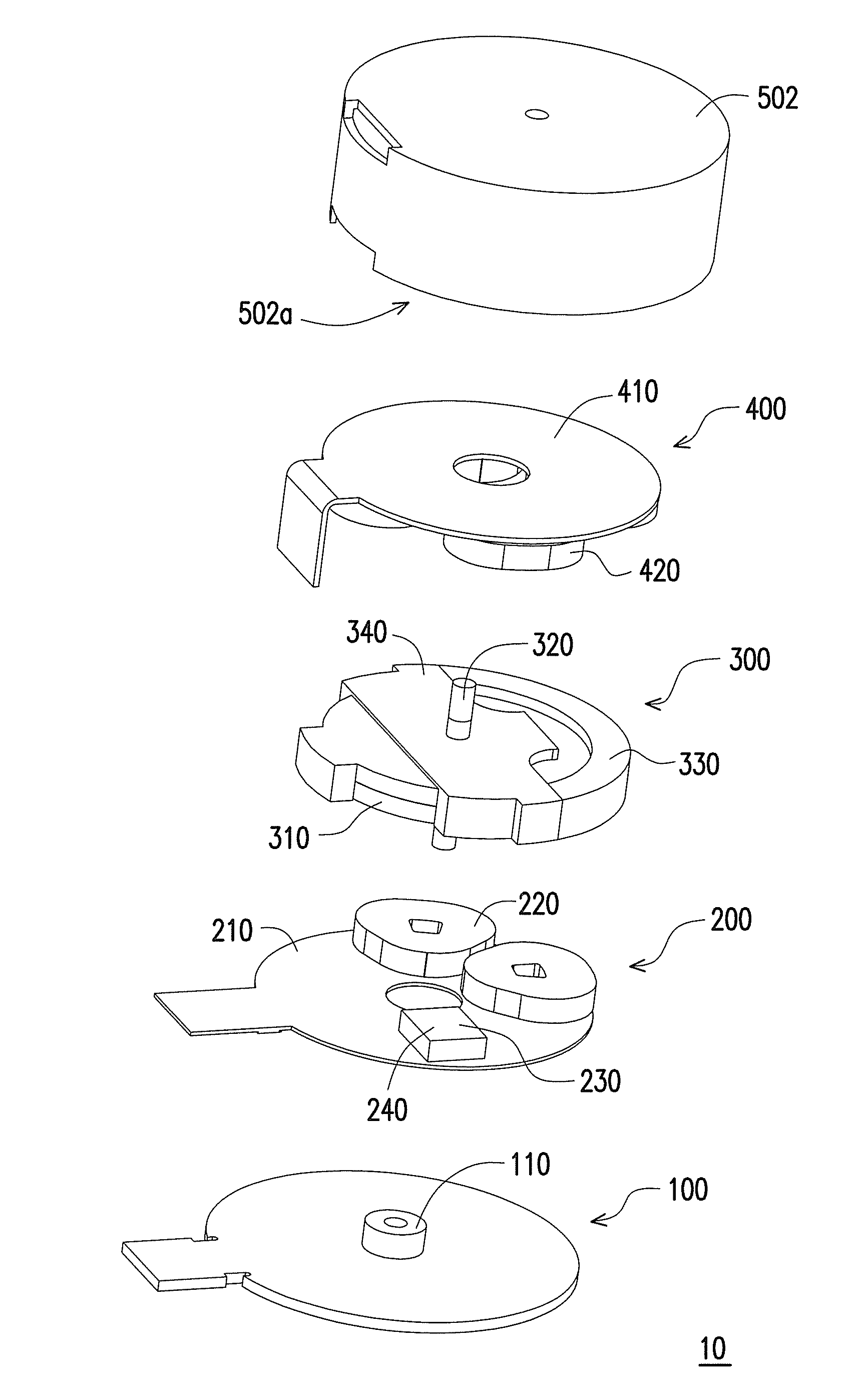
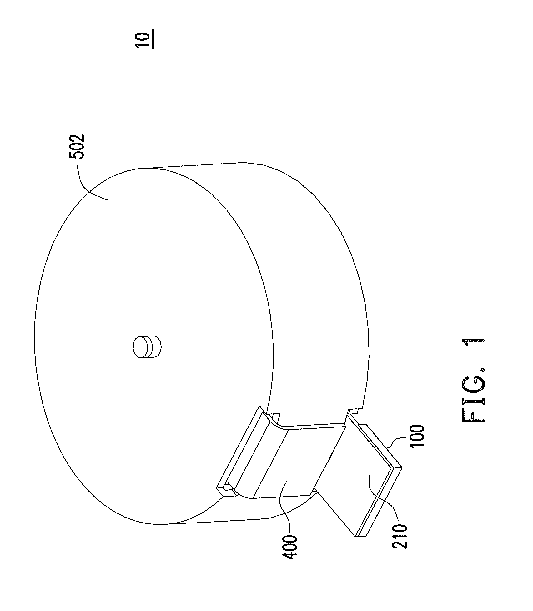
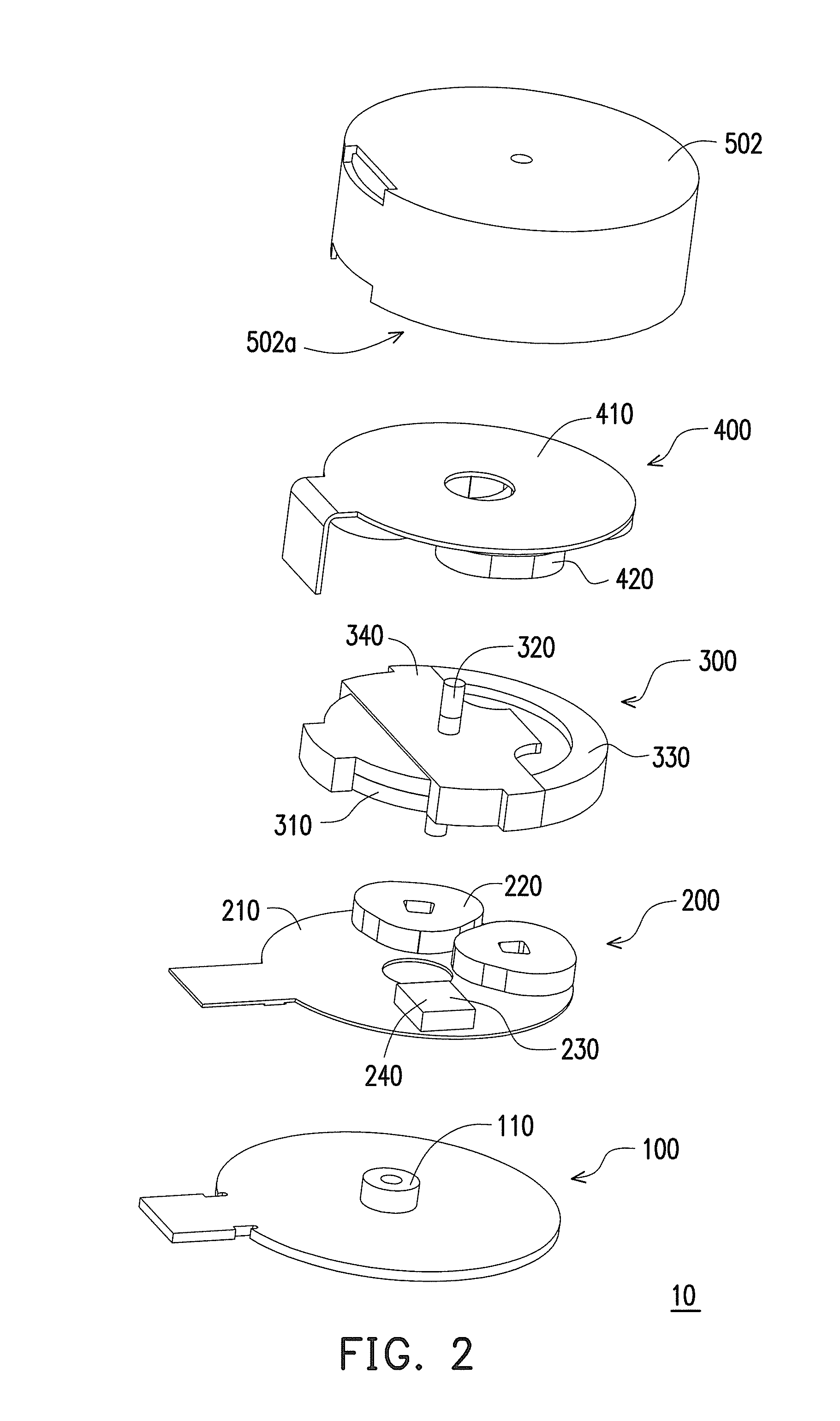
[0047]FIG. 1 is a schematic diagram illustrating a power generating device according to an embodiment of the present invention. FIG. 2 is an exploded view of the power generating device of FIG. 1. Referring to FIG. 1 and FIG. 2, the power generating device 10 is adapted to charge a handheld electronic device 20 (shown in FIG. 5). The power generating device 10 includes a carrier module 100, a stator module 200, a rotor module 300 and a power generating module 400. In the present embodiment, the power generating device 100 can further include a cover 502 assembled to the carrier module 100, which is used for protecting the aforementioned modules. In other words, the stator module 200, the rotor module...


PUM


Abstract

A power generating device includes a carrier module, a stator module, a rotor module and a power generating module. The stator module is assembled to the carrier module, and has a first circuit board and a plurality of driving coils. The rotor module is located in an electromagnetic field, and has a multipolar magnetic rotor and a rotating axle. A magnetic field of the multipolar magnetic rotor interacts with the electromagnetic field to make the rotor module rotating relative to the stator module, and make the multipolar magnetic rotor producing a varying magnetic field. The power generating module is located in the varying magnetic field, and has a second circuit board and a plurality of induction coils. The induction coils induct the varying magnetic field to output an induction circuit to the second circuit board.

Description

CROSS-REFERENCE TO RELATED APPLICATION[0001]This application claims the priority benefit of Taiwan application serial no. 98124140, filed on Jul. 16, 2009. The entirety of the above-mentioned patent application is hereby incorporated by reference herein and made a part of specification.BACKGROUND OF THE INVENTION[0002]1. Field of the Invention[0003]The present invention relates to a power generating device. More particularly, the present invention relates to a power generating device applied to a handheld electronic device.[0004]2. Description of Related Art[0005]A handheld electronic device refers to an electronic device that can be held and operated by a user, which has relatively small size and light weight for the user to carry around. A commonly used handheld electronic device is, for example, a mobile phone, a multimedia player, a personal digital assistant, a handheld computer, a handheld game machine and a handheld satellite navigator, etc.[0006]Since power required by the h...

Claims


Application Information

Patent Timeline
Patent Type & Authority Applications(United States)
IPC IPC(8): H02K47/04H02K7/06F03G5/06H02N2/18H02K53/00
CPCH02K7/063H02K7/116H02N2/18H02K35/02H02K7/1853
Inventor CHANG, CHI-LONECHIN, CHI-YUAN
Owner SILICON TOUCH TECH INC
Why Eureka
Try Eureka