Methods for Operation of a Touch Input Device

Inactive Publication Date: 2011-01-20
ZETTA RES & DEV LLC RPO SERIES
View PDF8 Cites 113 Cited by
  • Summary
  • Abstract
  • Description
  • Claims
  • Application Information

AI Technical Summary

Benefits of technology

[0010]It is an object of the present invention to overcome or ameliorate at leas

Problems solved by technology

For example resistive touch screens are inexpensive and can sense virtually any rigid touch object, but have poor screen viewability in bright light and can only sense single touches.
Projected capacitive has multi-touch capability but cannot sense a non-conductive stylus or a gloved finger, and likewise has poor screen viewability in bright light.
Optical has good screen viewability in bright l

Method used


Image

  • Methods for Operation of a Touch Input Device
  • Methods for Operation of a Touch Input Device
  • Methods for Operation of a Touch Input Device

Examples


Embodiment Construction

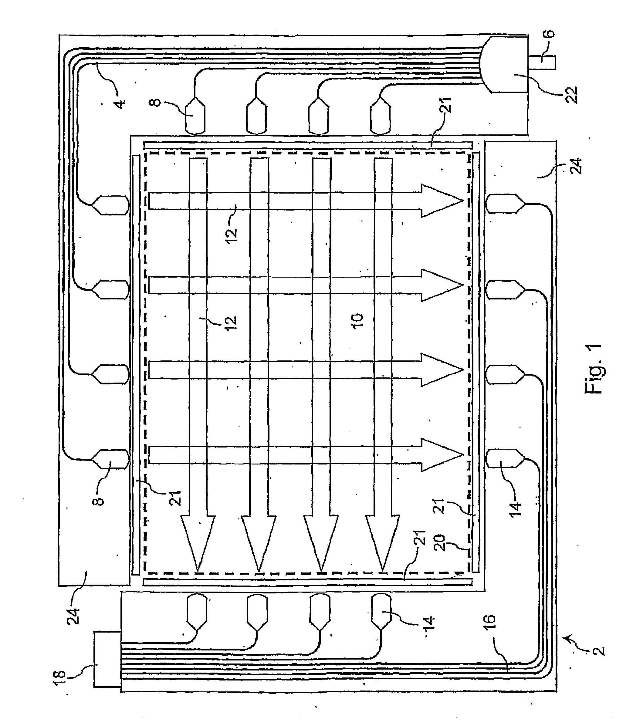
[0039]Referring to the drawings, FIG. 1 shows a touch input device 2 that uses a grid of light beams to detect a touch. Infrared light is typically used, but visible or ultraviolet light could also be used. In this style of touch input device, disclosed in U.S. Pat. No. 5,914,709 for example, integrated optical waveguides (‘transmit’ waveguides) 4 conduct light from a single optical source 6 to integrated in-plane lenses 8 that collimate the light in the plane of an input area 10 and launch a grid of light beams 12 across the input area. The light is collected by a second set of integrated in-plane lenses 14 and integrated optical waveguides (‘receive’ waveguides) 16 at the other side of the input area, and conducted to a position-sensitive (i.e. multi-element) detector 18. A touch object (e.g. a finger or stylus) cuts one or more of the beams of light and is detected as a shadow, with its position determined from the particular beam(s) blocked by the object. That is, the position o...


PUM


Abstract

The invention provides a method for operation of a touch input device comprising a touch input area. The method comprises the steps of (i) detecting a touch or near-touch of an object on or near said touch input area; (ii) determining a parameter indicative of the size and/or shape of said object; (iii) comparing said parameter with at least one predetermined value; and (iv) enabling an operational state of said touch input device in response to said comparison. The parameter may be compared with one or more threshold values which delimit the operational state of the input device. Such operational states include a sleep mode or active mode, the use of a full QWERTY or reduced keyboard, translation or rotation of graphical elements, etc. The method is particularly suitable for differentiating between a touch by a stylus or touch by a finger.

Description

FIELD OF THE INVENTION[0001]The present invention relates to methods for operation of a touch input device and in particular to methods of operation where the operational state of the touch input device is contingent upon the type; size or shape of a detected touch object. The invention has been developed primarily for use with touch input devices that include a display capable of presenting a plurality of user-selectable graphical elements, and will be described hereinafter with reference to this application. However, it will be appreciated that the invention is not limited to this particular field of use.BACKGROUND OF THE INVENTION[0002]Any discussion of the prior art throughout the specification should in no way be considered as an admission that such prior art is widely known or forms part of the common general knowledge in the field.[0003]Input devices based on touch sensing (touch screens) have long been used in electronic devices such as computers, personal digital assistants...

Claims


Application Information

Patent Timeline
IPC IPC(8): G06F3/041
CPCG06F3/018G06F3/0421H03K17/9629G06F3/04883G06F3/04886G06F3/04845
Inventor MAXWELL, IAN ANDREWKUKULJ, DAXMAUND, BRIGGATKINS, GRAHAM ROY
Owner ZETTA RES & DEV LLC RPO SERIES
Why Eureka
Try Eureka