Al technical title is built by PatSnap Al team. It summarizes the technical point description of the patent document.
a high-voltage battery pack, fail-safe technology, applied in secondary cell servicing/maintenance, batteries, cell components, etc., can solve the problems of reducing the range of vehicles, causing new problems or problems, and requiring replacement (exchange) mechanisms to be considered, so as to ensure the continuous operation of electric vehicles indefinitely
Active Publication Date: 2011-01-20
SCHEUCHER KARL F
View PDF2 Cites 167 Cited by
Summary
Abstract
Description
Claims
Application Information
AI Technical Summary
This helps you quickly interpret patents by identifying the three key elements:
Problems solved by technology
Method used
Benefits of technology
[0107]It is an object of the invention to enable continuous operation of electric vehic...
Problems solved by technology
Unlike combustion engine generation and regenerative braking, plug-in grid replenishment is only useable when the vehicle is at rest, in the proximity of an electrical outlet, and then only practical when the vehicle is to be parked for sonic period of time.
Several hurdles challenge this approach, however.
The fast recharge time comes with the penalty of heavier, larger, batteries and correspondingly reduced vehicle range.
However, there are new issues or problems created in the '423 patent disclosure.
One issue is the requirements placed upon the replacement (exchange) mechanisms contemplated, those mechanisms being semi-automatic and powerful in nature.
Another issue impeding the system contemplated in the '423 patent is the broad degree of battery standardization envisioned as a p...
Method used
Image
Click on the blue label to locate the original text in one second.
Reading with bidirectional positioning of images and text.
Examples
Embodiment Construction
and Claims which follow hereinbelow.
BRIEF DESCRIPTION OF THE DRAWINGS
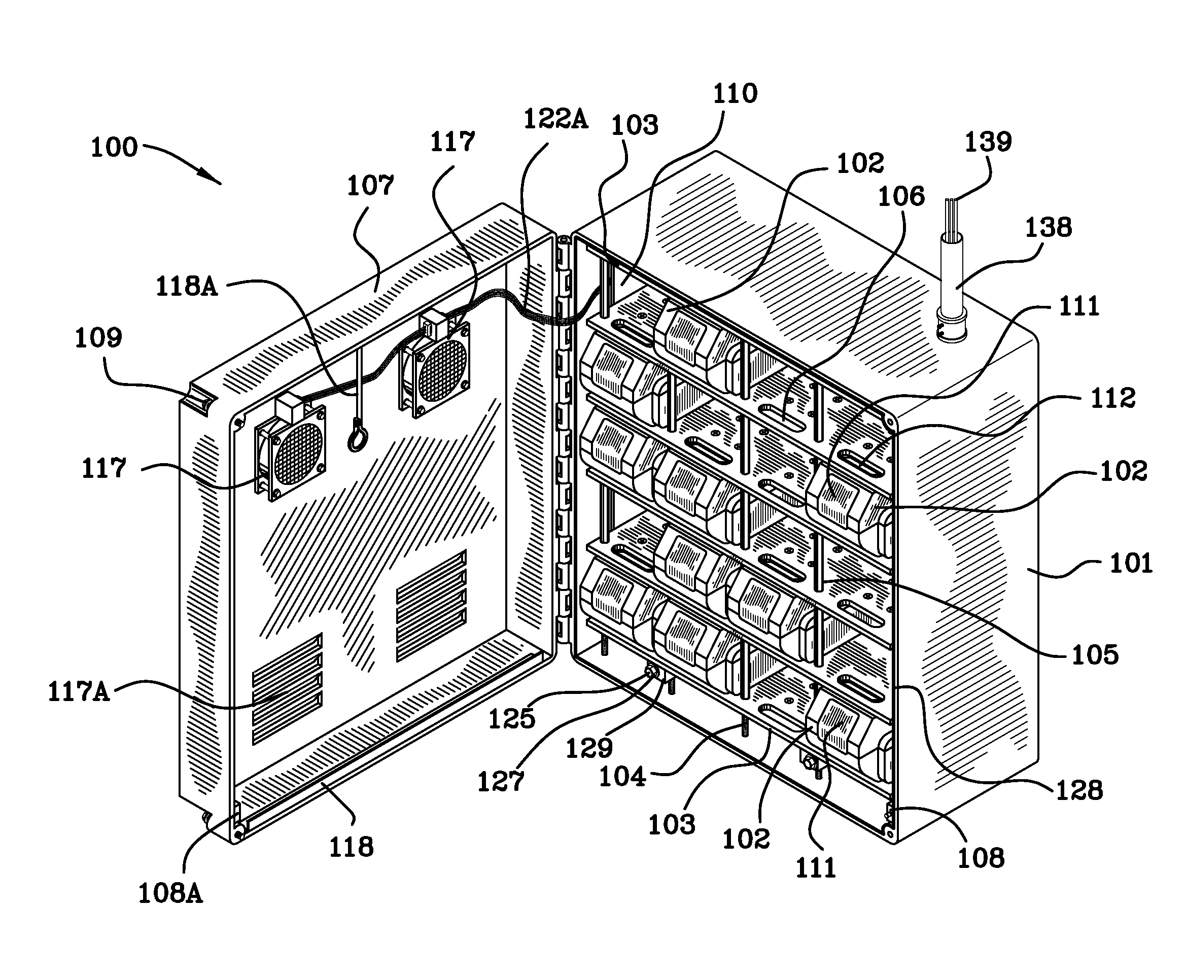
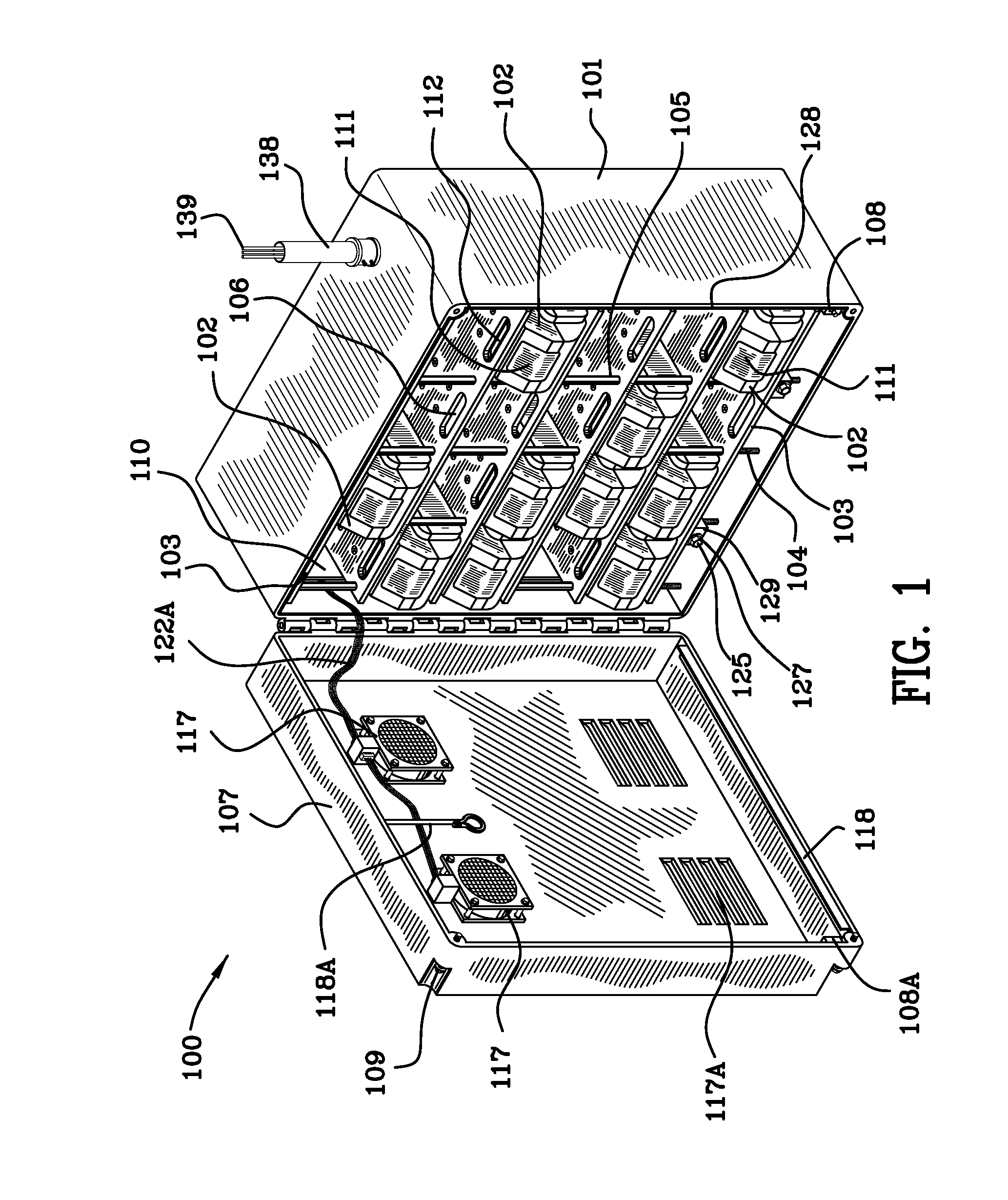
[0109]FIG. 1 is a front perspective view of the intelligent power supply device illustrating a plurality of removable cartridge energy packs in a rack.
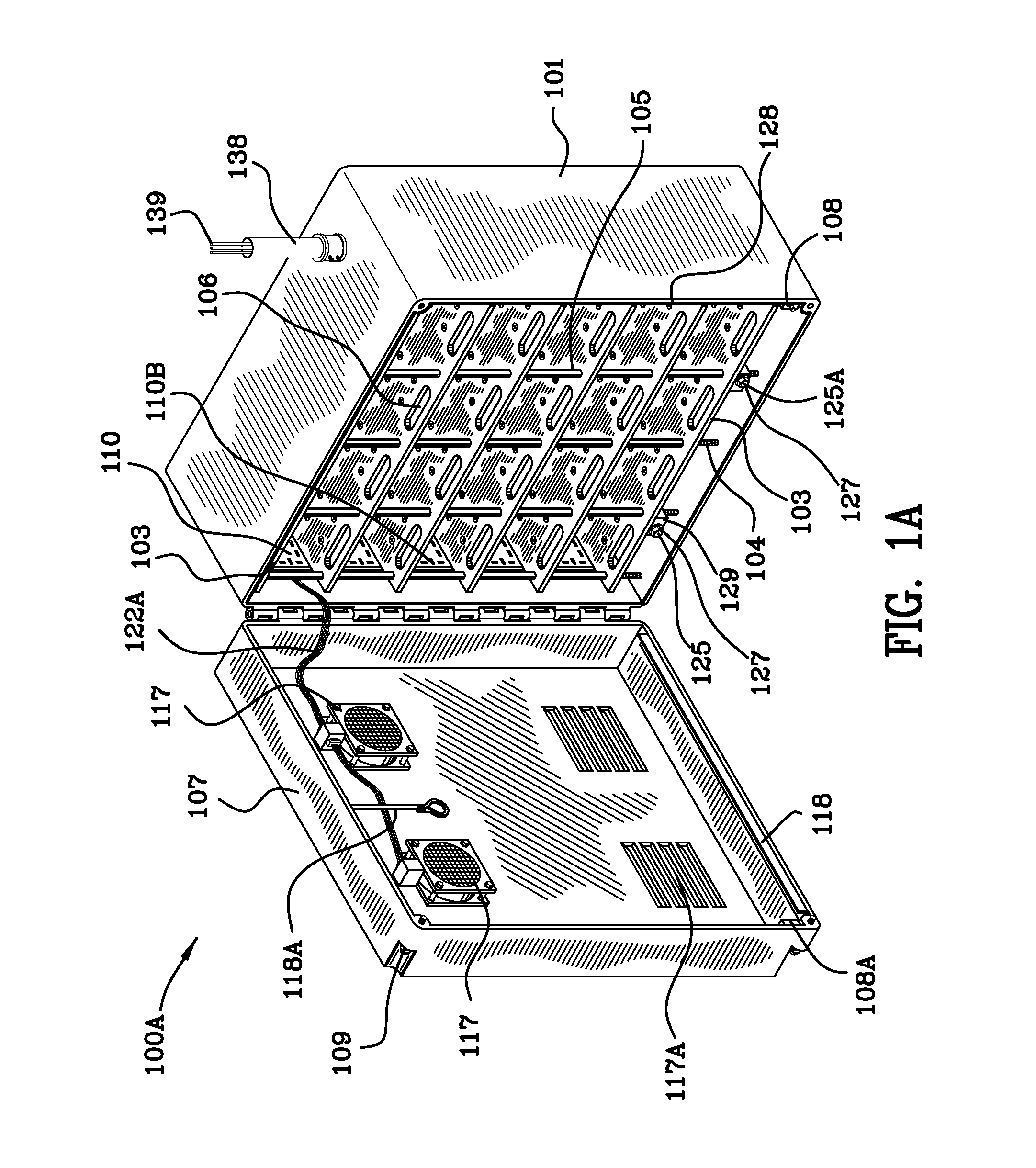
[0110]FIG. 1A is a front perspective view of the intelligent power supply device similar to FIG. I without the removable cartridge energy packs in the rack.
[0111]FIG. 1B is a front perspective view of the intelligent power supply device without the rack and without the removable cartridge energy packs in the rack.
[0112]FIG. 1C is a front perspective view of the rack illustrated in FIGS. 1 and 1A.
[0113]FIG. 1D is a front view of the rack partially populated with the removable cartridge energy packs in the rack.
[0114]FIG. 1E is a side view of the rack taken along the lines 1E-1E of FIG. 1D.
[0115]FIG. 1F is a side view of the rack taken along the lines 1F-1F of FIG. 1D.
[0116]FIG. 1G is an enlargement of a portion of FIG. 1D illustrating one of the removable cartridge en...
PUM
Abstract
A fail safe battery pack is disclosed and claimed wherein first and second housings are affixed together. A plurality of battery cells reside within and fixedly engage the first and the second housings. First and second. printed circuit boards (PCBs) reside within first and second lattice structures of the first and second housings. A variable bias device resides in the first and/or second lattice structure of the first and second housing and engages the first and/or second PCBs. When the bias of the variable bias device is sufficiently large it overcomes a plurality of fixed mechanically biased devices operating between the PCB and the plurality of battery cells and tending to separate same and causes the PCB to electrically communicate with the plurality of battery cells. When the bias of the variable bias device is sufficiently small, the plurality of fixed mechanically biased devices separates the PCB and the plurality of battery cells rendering the battery cells in an electrically safe condition.
Description
[0001]This patent application is a continuation in part of copending U.S. patent application Ser. No. 11 / 851,504 and claims priority to copending U.S. application Ser. No. 11 / 851,504 filed Sep. 7, 2007. This patent application is a non-provisional of U.S. provisional patent application Ser. No. 61,242,782 and claims priority to U.S. provisional patent application Ser. No. 61,242,782 filed Sep. 15, 2009. Karl F. SCHEUCHER is the inventor of the instant application, U.S. patent application Ser. No. 11 / 851,504 and U.S. provisional patent application Ser. No. 61,242,782. U.S. patent application Ser. No. 11 / 851,504 is: a continuation in-part of utility patent application Ser. No. 11 / 672,853, filed Feb. 8, 2007, continuation-in-part of utility patent application Ser. No. 11 / 672,957 filed Feb. 8, 2007, and, is a continuation-in-part of utility patent application Ser. No. 11 / 673,551 filed Feb. 9, 2007, all of which claim priority to provisional patent application Ser. Nos. 60 / 771,771 filed ...
Claims
Application Information
Patent Timeline
Application Date:The date an application was filed.
Publication Date:The date a patent or application was officially published.
First Publication Date:The earliest publication date of a patent with the same application number.
Issue Date:Publication date of the patent grant document.
PCT Entry Date:The Entry date of PCT National Phase.
Estimated Expiry Date:The statutory expiry date of a patent right according to the Patent Law, and it is the longest term of protection that the patent right can achieve without the termination of the patent right due to other reasons(Term extension factor has been taken into account ).
Invalid Date:Actual expiry date is based on effective date or publication date of legal transaction data of invalid patent.