Continuously variable transmission and control method thereof

a transmission and variable technology, applied in the direction of gearing control, gearing elements, gearing, etc., can solve the problems of delay in driving force increase, shift feeling deterioration, and large amount of time, and achieve the effect of rapid driving force increase and shift feeling improvemen

Active Publication Date: 2011-01-20
JATCO LTD +1
View PDF23 Cites 29 Cited by
  • Summary
  • Abstract
  • Description
  • Claims
  • Application Information

AI Technical Summary

Benefits of technology

[0009]According to these aspects, when the accelerator pedal is depressed such that a second speed kick down shift accompanied by modification of the gear position of the subtransmission mechanism from the second gear position to the first gear position is perf

Problems solved by technology

However, when the need to modify the gear position of the subtransmission mechanism arises during the kick down shift while a coordinated shift is und

Method used


Image

  • Continuously variable transmission and control method thereof
  • Continuously variable transmission and control method thereof
  • Continuously variable transmission and control method thereof

Examples


Embodiment Construction

[0018]An embodiment of this invention will be described below with reference to the attached figures. It should be noted that in the following description, a “speed ratio” of a certain speed change mechanism is a value obtained by dividing an input rotation speed of the speed change mechanism by an output rotation speed of the speed change mechanism. Further, a “Lowest speed ratio” is a maximum speed ratio of the speed change mechanism and a “Highest speed ratio” is a minimum speed ratio of the speed change mechanism.

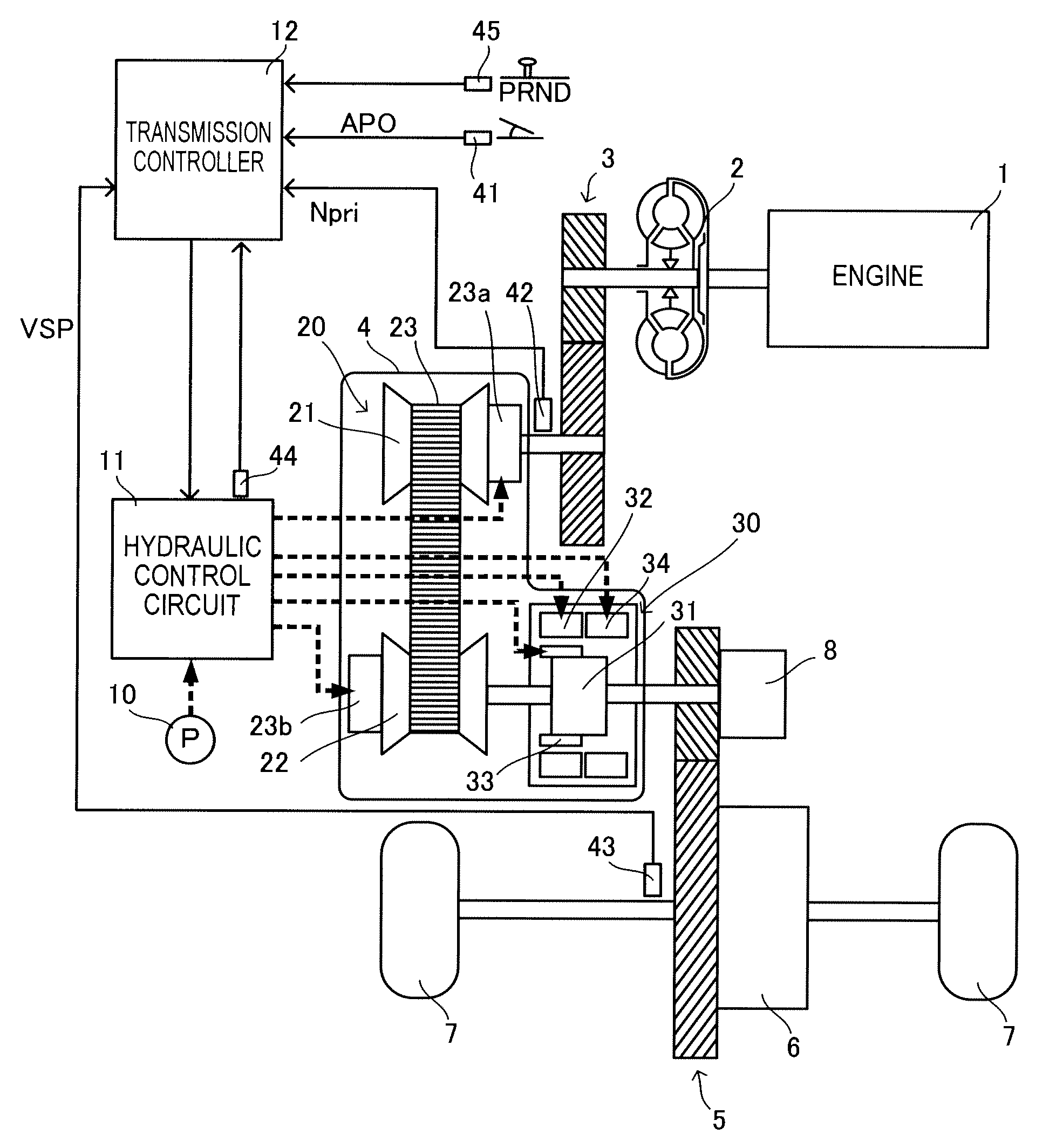
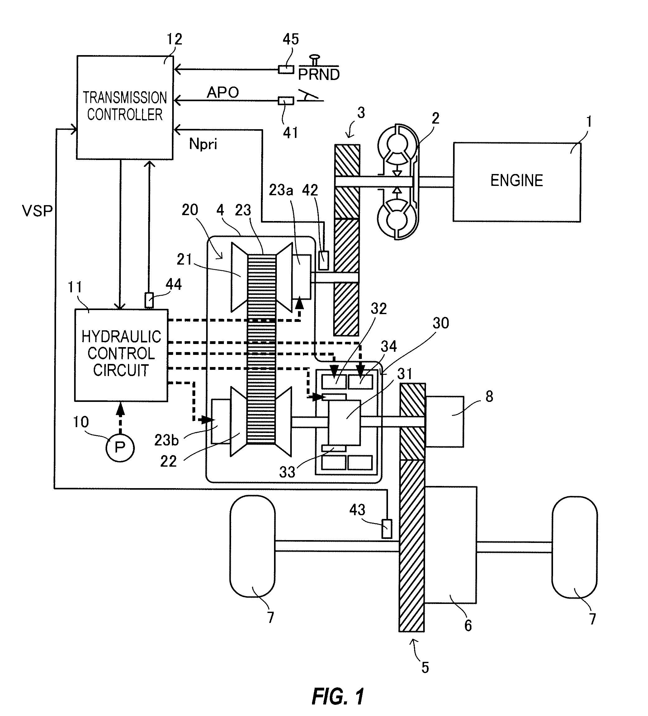
[0019]FIG. 1 is a schematic diagram showing a vehicle installed with a continuously variable transmission according to an embodiment of this invention. The vehicle includes an engine 1 as a power source. An output rotation of the engine 1 is transmitted to drive wheels 7 via a torque converter 2 including a lockup clutch, a first gear train 3, a continuously variable transmission (to be referred to simply as a “transmission 4” hereafter), a second gear train 5, and a fi...


PUM


Abstract

The transmission controller performs a non-coordinated shift, in which the gear position of the subtransmission mechanism is modified from the second gear position to the first gear position at a higher speed than when the gear position of the subtransmission mechanism is modified by a coordinated shift while permitting a deviation between the through speed ratio and the target through speed ratio, instead of the coordinated shift when it is determined that the second speed kick down shift is to be performed.

Description

TECHNICAL FIELD OF THE INVENTION[0001]This invention relates to a continuously variable transmission and a control method thereof, and more particularly to a continuously variable transmission comprising a continuously variable speed change mechanism and a subtransmission mechanism.BACKGROUND OF THE INVENTION[0002]JP60-37455A discloses a continuously variable transmission in which a two-forward speed subtransmission mechanism is provided in series with a continuously variable speed change mechanism (to be referred to hereafter as a “variator”), and a gear position of the subtransmission mechanism is changed in accordance with an operating condition of a vehicle. Thus, an achievable speed ratio range is enlarged without increasing the size of the variator.[0003]JP5-79554A discloses control (to be referred to hereafter as a “coordinated shift”) employed in this type of continuously variable transmission including a subtransmission mechanism which varies a speed ratio of the variator i...

Claims


Application Information

Patent Timeline
IPC IPC(8): B60W10/10F16H37/02F16H59/18F16H61/00F16H61/02F16H61/70
CPCF16H37/022F16H59/20F16H61/66259F16H61/702Y10T477/619Y10T477/6242Y10T477/6217Y10T477/693675Y10T477/623F16H2037/023F16H61/66272
Inventor NONOMURA, RYOUSUKETANAKA, HIROYASUINOUE, TAKUICHIROSEKI, JOUJIINOUE, MAMIKOTAKAHASHI, SEIICHIRO
Owner JATCO LTD
Why Eureka
Try Eureka