Automatic transmission apparatus

a transmission apparatus and automatic technology, applied in mechanical devices, transportation and packaging, gear shifting, etc., can solve the problems of reducing the transmission efficiency of power, affecting the smooth shift feel around the time, and increasing the loss of meshing gears, so as to improve the acceleration performance, fuel economy, and fuel economy.

Inactive Publication Date: 2016-07-14
AISIN AW CO LTD +1
View PDF0 Cites 4 Cited by
  • Summary
  • Abstract
  • Description
  • Claims
  • Application Information

AI Technical Summary

Benefits of technology

[0039]The above-described structure allows the automatic transmission apparatus to perform shifting to each of the first to the tenth forward speeds and the reverse speed using the four planetary gear mechanisms, the four clutches, and the two brakes. As a result, the automatic transmission apparatus of the present invention can have a larger number of forward shift speeds than that of the automatic transmission apparatus of the conventional example that can perform shifting to each of the first to the seventh forward speeds and the reverse speed, thereby providing better fuel economy than that of the automatic transmission apparatus of the conventional example, while achieving all of better fuel economy, better acceleration performance, and better shift feel of the vehicle including the automatic transmission apparatus. The automatic transmission apparatus of the present invention can also perform shifting to optimal gear stages, thereby improving the shift feel.
[0040]As described above, each of the first to the tenth forward speeds and the reverse speed is established by engaging three engagement elements and disengaging the other three engagement elements of the six engagement elements including the four clutches and the two brakes, so that the number of the engagement elements to be disengaged can be reduced compared to that of the automatic transmission apparatus of the conventional example that engages two engagement elements and disengages the other four engagement elements of the six engagement elements. The engagement elements generate a drag loss due to slight contact even while disengaged, so that the drag loss reduces the transmission efficiency of power to a lower level as a larger number of engagement elements are disengaged when each of the shift speeds is established. The automatic transmission apparatus of the present invention disengages fewer engagement elements than those of the automatic transmission apparatus of the conventional example, thereby having a higher transmission efficiency of power than that of the automatic transmission apparatus of the conventional example.
[0041]The automatic transmission apparatus of the present invention described above can also be characterized in that each of the first, the second, the third, and the fourth planetary gear mechanisms is structured as a single-pinion type planetary gear mechanism having a sun gear, a ring gear, and a carrier as the three rotational elements, in that each of the first, the fourth, the seventh, and the tenth rotational elements is a sun gear, in that each of the second, the fifth, the eighth, and the eleventh rotational elements is a carrier, and in that each of the third, the sixth, the ninth, and the twelfth rotational elements is a ring gear. In other words, all the four planetary gear mechanisms are structured as single-pinion type planetary gear mechanisms. A double-pinion type planetary gear mechanism includes two rows of pinion gears in a radial direction. As a result, the pinion gears mesh with each other, so that the meshing loss of gears is increased, and thus the transmission efficiency of power is reduced compared to the case of the single-pinion type planetary gear mechanisms. Because of having the two rows of pinion gears in the radial direction, the double-pinion type planetary gear mechanism has a larger number of components, lower assemblability, and a lower economic efficiency than in the case of the single-pinion type planetary gear mechanisms. All the four planetary gear mechanisms in the automatic transmission apparatus of the present invention are structured as single-pinion type planetary gear mechanisms. As a result, the automatic transmission apparatus of the present invention can have a higher transmission efficiency of power, better assemblability, a lower cost burden, and a smaller mass than in the case of the automatic transmission apparatus of the conventional example in which three of the four planetary gear mechanisms are structured as single-pinion type planetary gear mechanisms and the remaining one is structured as a double-pinion type planetary gear mechanism.
[0042]The automatic transmission apparatus of the present invention can also be characterized in that the second brake is structured as a dog brake. The dog brake is likely to cause a shock when engaged, and hence needs to be synchronously controlled to synchronize the rotation thereof. However, the second brake is engaged at the first forward speed and the reverse speed, and hence is easily controlled because of being synchronously controlled at a low rotational speed. The second brake is continuously engaged at the first to the fifth forward speeds, and is disengaged at the sixth forward speed, which is relatively high-geared, so that employing the dog brake does not impair the shift feel.

Problems solved by technology

However, a large step ratio (the gear ratio of the one-step lower shift speed / the gear ratio of the current shift speed) impairs a smooth shift feel around the time of shifting.
As a result, the pinion gears mesh with each other, so that the meshing loss of gears is increased, and thus the transmission efficiency of power is reduced compared to the case of the single-pinion type planetary gear mechanisms.
Because of having the two rows of pinion gears in the radial direction, the double-pinion type planetary gear mechanisms have a larger number of components, lower assemblability, a higher cost burden, and a larger mass than in the case of the single-pinion type planetary gear mechanisms.
The engagement elements of the automatic transmission apparatus generate a drag loss due to slight contact even while disengaged, so that the drag loss reduces the transmission efficiency of power to a lower level as a larger number of engagement elements are disengaged when a shift speed is established.

Method used


Image

  • Automatic transmission apparatus
  • Automatic transmission apparatus
  • Automatic transmission apparatus

Examples


embodiment

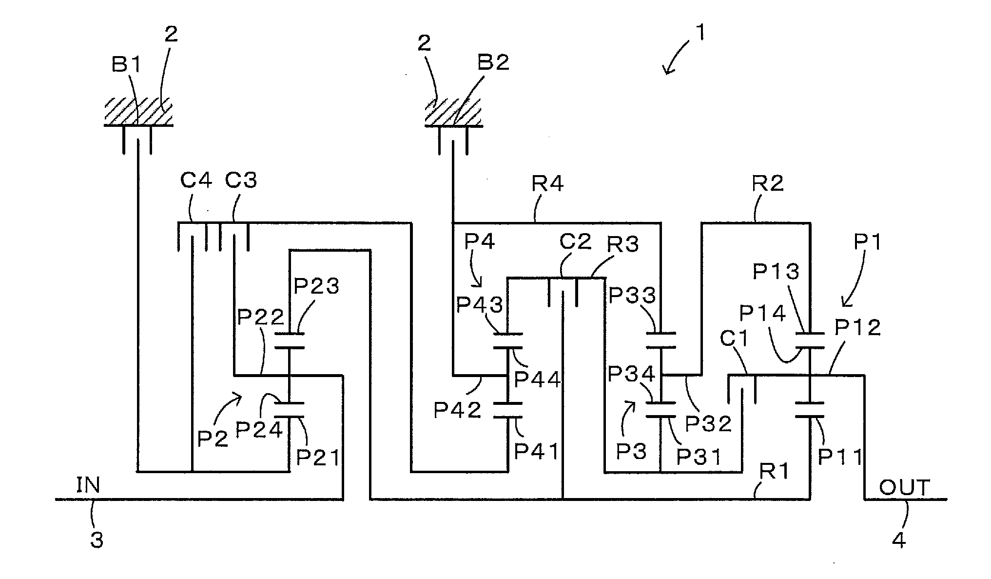
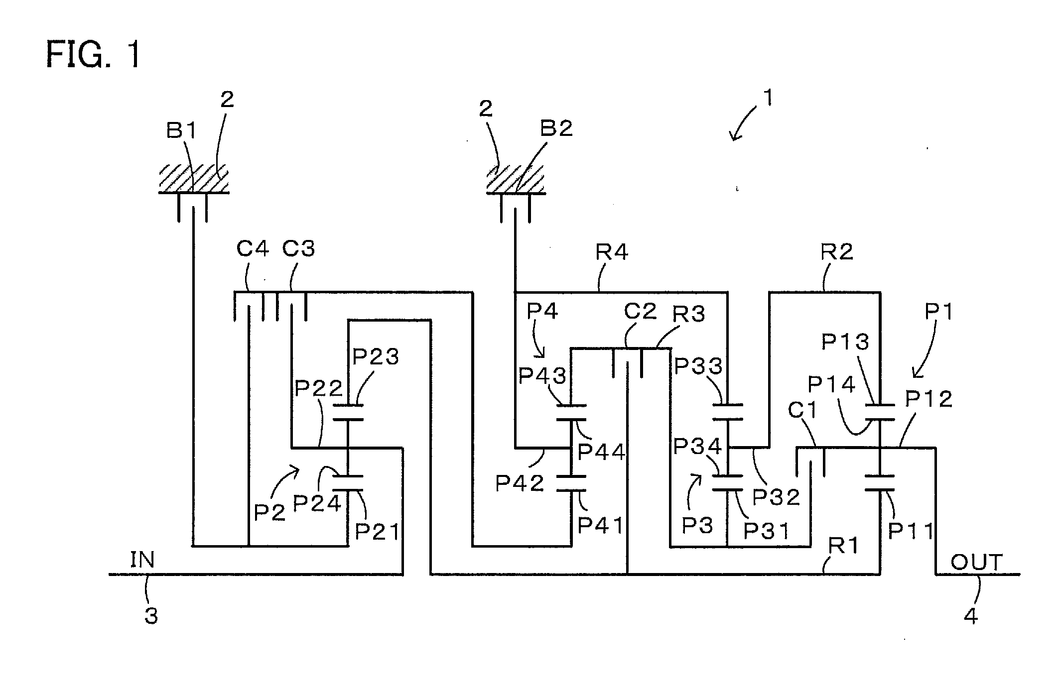
[0048]FIG. 1 is a structural diagram showing an outline of an automatic transmission apparatus 1 as an embodiment of the present invention. The automatic transmission apparatus 1 of the embodiment includes four single-pinion type planetary gear mechanisms P1, P2, P3, and P4, four clutches C1, C2, C3, and C4, and two brakes B1 and B2, and is mounted on a vehicle of a type (such as a front-engine rear-drive type) in which an engine as an internal combustion engine (not shown) is longitudinally arranged (in the front-rear direction of the vehicle). The automatic transmission apparatus 1 is structured as a stepped speed change mechanism that receives power from the engine via a starting device, such as a torque converter (not shown) from an input shaft 3, and also shifts the received power to be output to an output gear 4. The power output to the output shaft 4 is output to right and left driving wheels via a gear mechanism and a differential gear (not shown). In the automatic transmiss...


PUM


Abstract

An automatic transmission apparatus that includes a first planetary gear mechanism, a second planetary gear mechanism, a third planetary gear mechanism, a fourth planetary gear mechanism, a first coupling element, a second coupling element, a third coupling element, a fourth coupling element, a first clutch, a second clutch, a third clutch, a fourth clutch, a first brake and a second brake.

Description

TECHNICAL FIELD[0001]The present invention relates to an automatic transmission apparatus that shifts power input to an input member and outputs the shifted power to an output member.BACKGROUND ART[0002]An automatic transmission apparatus of this type has heretofore been proposed which can establish seven forward speeds and a reverse speed using four planetary gear mechanisms and six engagement elements including three clutches and three brakes (refer to Patent Document 1, for example). An automatic transmission apparatus of the conventional example as a background art includes, as the four planetary gear mechanisms, a double-pinion type planetary gear mechanism having a gear ratio (the number of teeth of the sun gear / the number of teeth of the ring gear in the planetary gear mechanism) of 0.544 and three single-pinion type planetary gear mechanisms having gear ratios of 0.439, 0.310, and 0.535, and establishes the seven forward speeds and the reverse speed by engaging two engagemen...

Claims


Application Information

Patent Timeline
Patent Type & Authority Applications(United States)
IPC IPC(8): F16H3/66
CPCF16H3/66F16H2200/0069F16H2200/2094F16H2200/2046F16H2200/2064F16H2200/2012
Inventor KATO, TAKAYOSHIMORIMOTO, TAKASHIAOKI, TOSHIHIKOKATO, HIROSHIKASUYA, SATORUMORISE, MASARUOITA, SHINJI
Owner AISIN AW CO LTD
Why Eureka
Try Eureka