
Transmission equipped with cable-type shift device

a technology of shift device and transmission cable, which is applied in the direction of mechanical control device, manual control with single controlling member, instruments, etc., can solve the problems of affecting the smooth support, and affecting the shift feeling, so as to improve the shift feeling and support the counterweight smoothly. , the effect of improving the shift feeling

Inactive Publication Date: 2006-04-13
MAZDA MOTOR CORP
View PDF3 Cites 3 Cited by
  • Summary
  • Abstract
  • Description
  • Claims
  • Application Information

AI Technical Summary

Benefits of technology

[0006] The present invention has been devised in view of the above-described problems. An object of the present invention is to provide the transmission equipped with a cable-type shift device which can support the counterweight smoothly and improve the shift feeling properly with a relatively small force for the select-direction operation of the change lever. Another object of the present invention is to provide the transmission equipped with a cable-type shift device which can utilize the space properly.
[0007] According to the present invention, there is provided a transmission equipped with a cable-type shift device, comprising a control shaft operative to control a shift change with rotation and axial-direction movement thereof in a case of the transmission, an outer lever operative to be rotated by a shift-direction operation of a change lever, the outer lever being fixed to the control shaft outside the case of the transmission and coupled to the change lever via a cable, and a counterweight operative to rotate with the rotation of the control shaft, but not to move with the axial-direction movement of the control shaft, wherein the counterweight includes a first weight portion and a second weight portion, an arm portion to interconnect the first and second weight portions, and a support axis disposed so as to extend vertically apart from the control shaft, and the support axis rotatably supports a substantial gravity center of an entire of the first and second weight portions and the arm portion. Accordingly, the shift feeling can be improved, and the counterweight can be supported smoothly because the middle portion of the arm portion interconnecting two weight are supported. Also, since the counterweight is constituted so as not to move in the axial direction of the control shaft, the select-direction operation of the change lever can be done with the relatively small force.
[0008] According to a preferred embodiment of the present invention, the first weight portion is heavier than the second weight portion, a first portion of the arm portion which interconnects the support axis and the first weight portion is shorter than a second portion of the arm portion which interconnects the axis support and the second weight portion, and there is further provided a link member which interconnects the second arm of the arm portion and the outer lever and thereby makes the counterweight rotate with the rotation of the outer lever. Accordingly, both efficient space utilization and weight reduction of the counterweight can be attained.

Problems solved by technology

Accordingly, a relatively large moment caused by the counterweight acts on the rotational axis, so that a smooth support would be deteriorated with the frequent rotation.
Also, since the counterweight is constituted so as to move vertically with select-direction operation of the change lever in the conventional device, the select-direction operation of the change lever would require a relatively large force, and thereby the shift feeling would not be appropriate.

Method used


Image

  • Transmission equipped with cable-type shift device
  • Transmission equipped with cable-type shift device
  • Transmission equipped with cable-type shift device

Examples


Embodiment Construction

[0021] Hereinafter, an exemplified preferred embodiment of the present invention will be described in detail referring to the accompanied drawings. Herein, the following discloses just the exemplified embodiment, and the present invention should not to be limited to this embodiment.

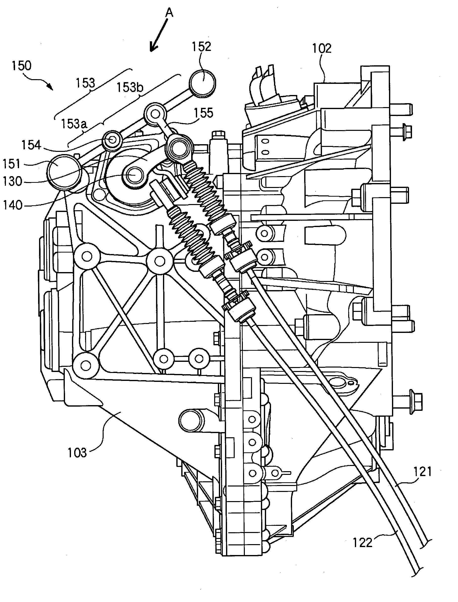
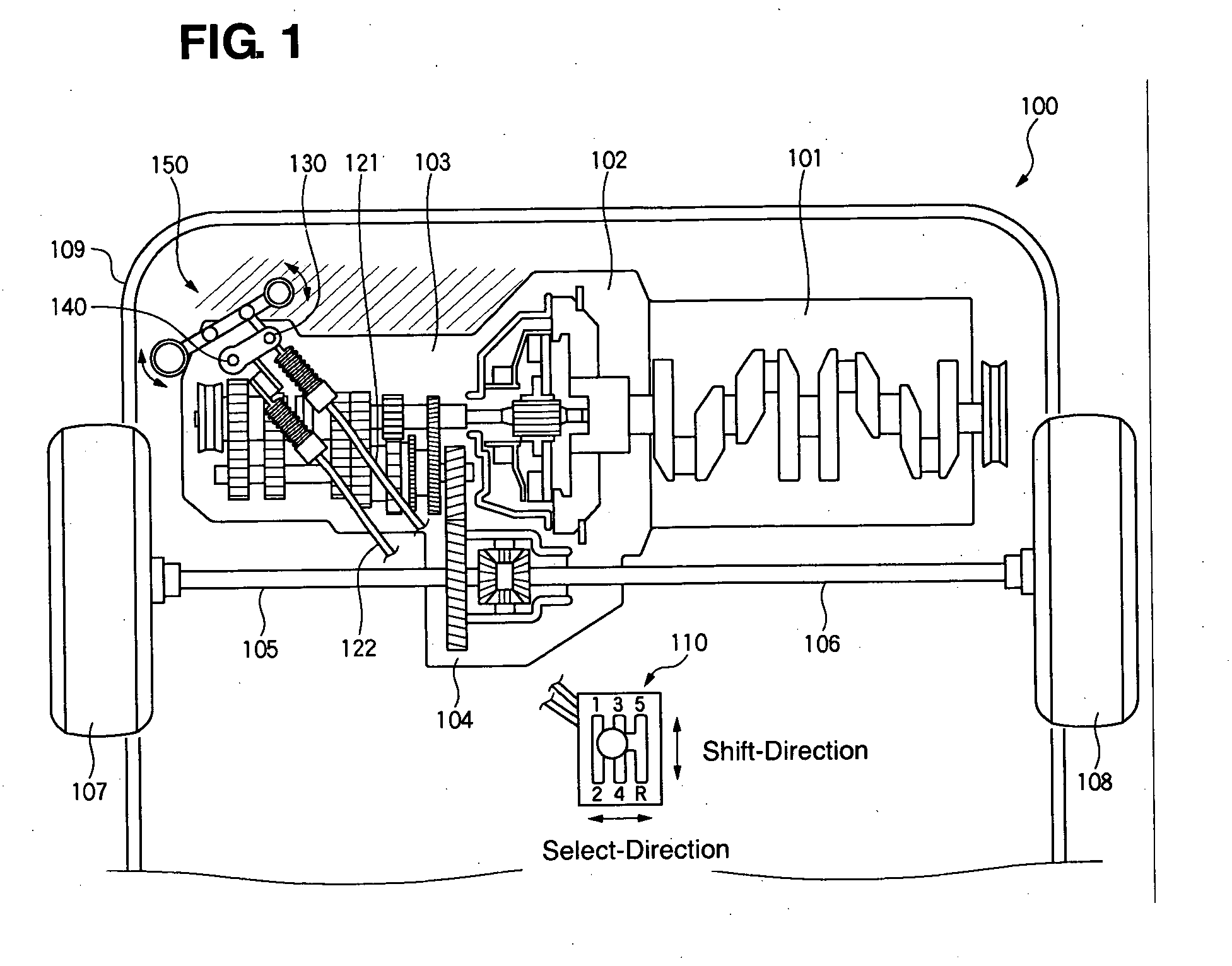
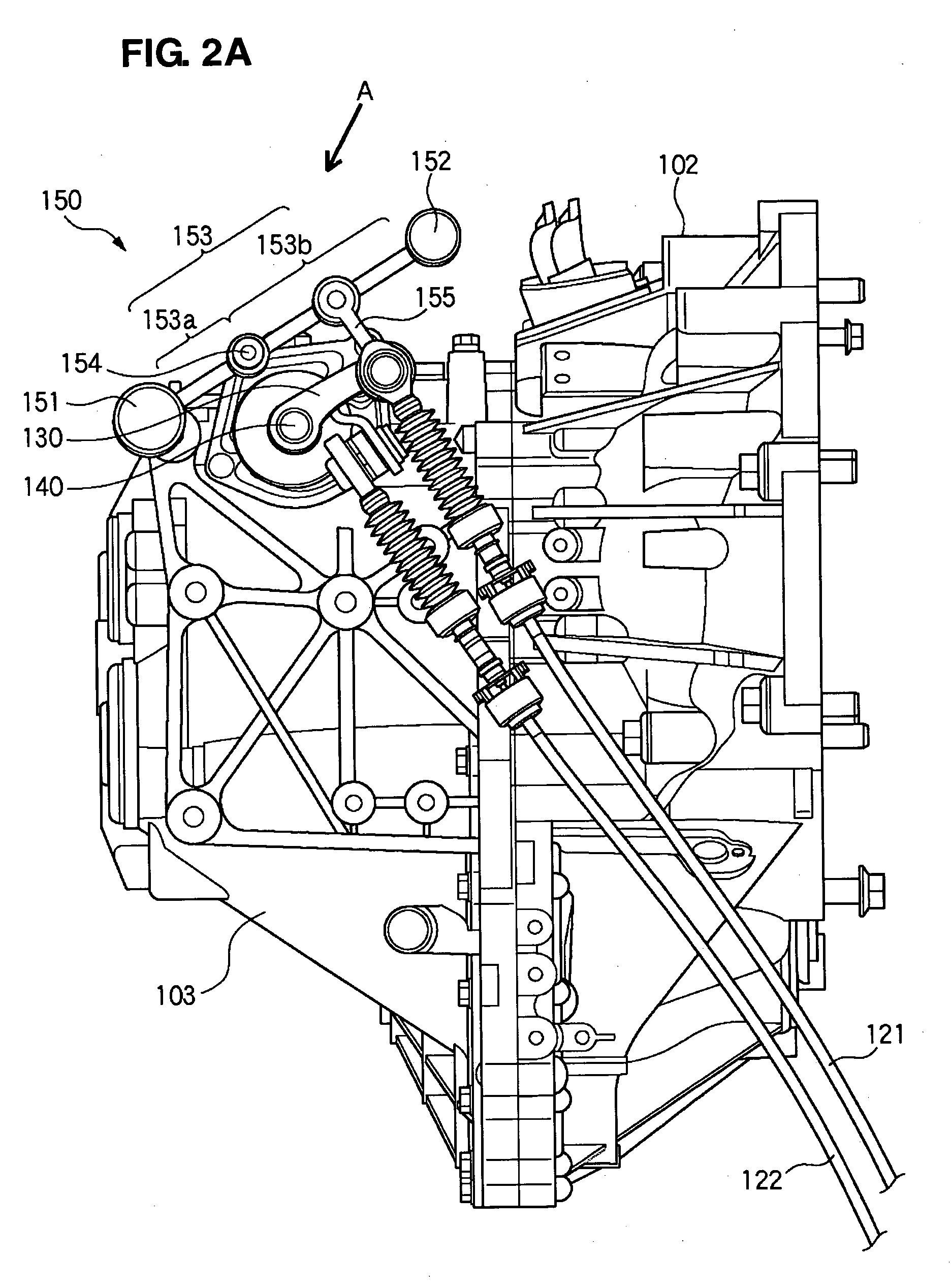
[0022]FIG. 1 is a schematic view of an engine room, viewed from above, of a vehicle 100 equipped with a transmission according to an embodiment of the present invention. In the present embodiment, the transmission in which an laterally-disposed engine and a FF vehicle with a five-stage manual transmission are applied will be described as an example.

[0023] As illustrated in this figure, there is provided an engine 101 in an engine room of the vehicle 100, and a transmission 103 is coupled to the engine 101 via a clutch 102. A rotation of an output shaft of the transmission 103 is transmitted to a differential gear 104 and then to drive wheels 107, 108 via drive shafts 105, 106. The transmission 103 is di...


PUM


Abstract

A transmission equipped with a cable-type shift device comprises a control shaft to control a shift change with rotation and axial-direction movement thereof, an outer lever to be rotated by a shift-direction operation of a change lever, and a counterweight to rotate with the rotation of the control shaft, but not to move with the axial-direction movement of the control shaft. The counterweight includes first and second weight portions, an arm portion to interconnect these weight portions, and a support axis disposed so as to extend vertically. The support axis rotatably supports a substantial gravity center of the first and second weight portions and the arm portion. Accordingly, the counterweight can be supported smoothly and the shift feeling can be improved properly with a relatively small force for the select-direction operation of the change lever.

Description

BACKGROUND OF THE INVENTION [0001] The present invention relates to a transmission equipped with a cable-type shift device. [0002] Conventionally, the transmission equipped with the cable-type shift device is known (see, for example, U.S. Pat. No. 5,791,194). In this kind of shift device, a counterweight is constituted so as to rotate with operation of a change lever, and an inertia of the counterweight improves shift feeling. [0003] However, in the conventional shift device, the counterweight is provided at one tip end of a support arm which is supported at a rotational axis. Accordingly, a relatively large moment caused by the counterweight acts on the rotational axis, so that a smooth support would be deteriorated with the frequent rotation. [0004] Also, since the counterweight is constituted so as to move vertically with select-direction operation of the change lever in the conventional device, the select-direction operation of the change lever would require a relatively large f...

Claims


Application Information

Patent Timeline
Patent Type & Authority Applications(United States)
IPC IPC(8): F16C1/10
CPCF16H61/24F16H61/36Y10T74/20049Y10T74/20018F16H2061/246
Inventor OKADOME, YASUKI
Owner MAZDA MOTOR CORP
Learn More