Sequential automatic transmission

a technology of automatic transmission and gearbox, applied in the direction of gearing control, gearing element, belt/chain/gearing, etc., can solve problems such as giving a driver discomfort, and achieve the effect of reducing the load of the clutch and improving the shift feeling

Inactive Publication Date: 2007-10-04
HONDA MOTOR CO LTD
View PDF13 Cites 6 Cited by
  • Summary
  • Abstract
  • Description
  • Claims
  • Application Information

AI Technical Summary

Benefits of technology

[0006] The invention has been made in view of such drawbacks of the prior art, and it is an object of the invention to provide a sequential automatic transmission which can realize the enhancement of a shift feeling and the reduction of load of the clutch.

Problems solved by technology

Thus, there may be a situation in which a large engine brake is generated thus giving a discomfort to a driver.

Method used


Image

  • Sequential automatic transmission
  • Sequential automatic transmission
  • Sequential automatic transmission

Examples


Embodiment Construction

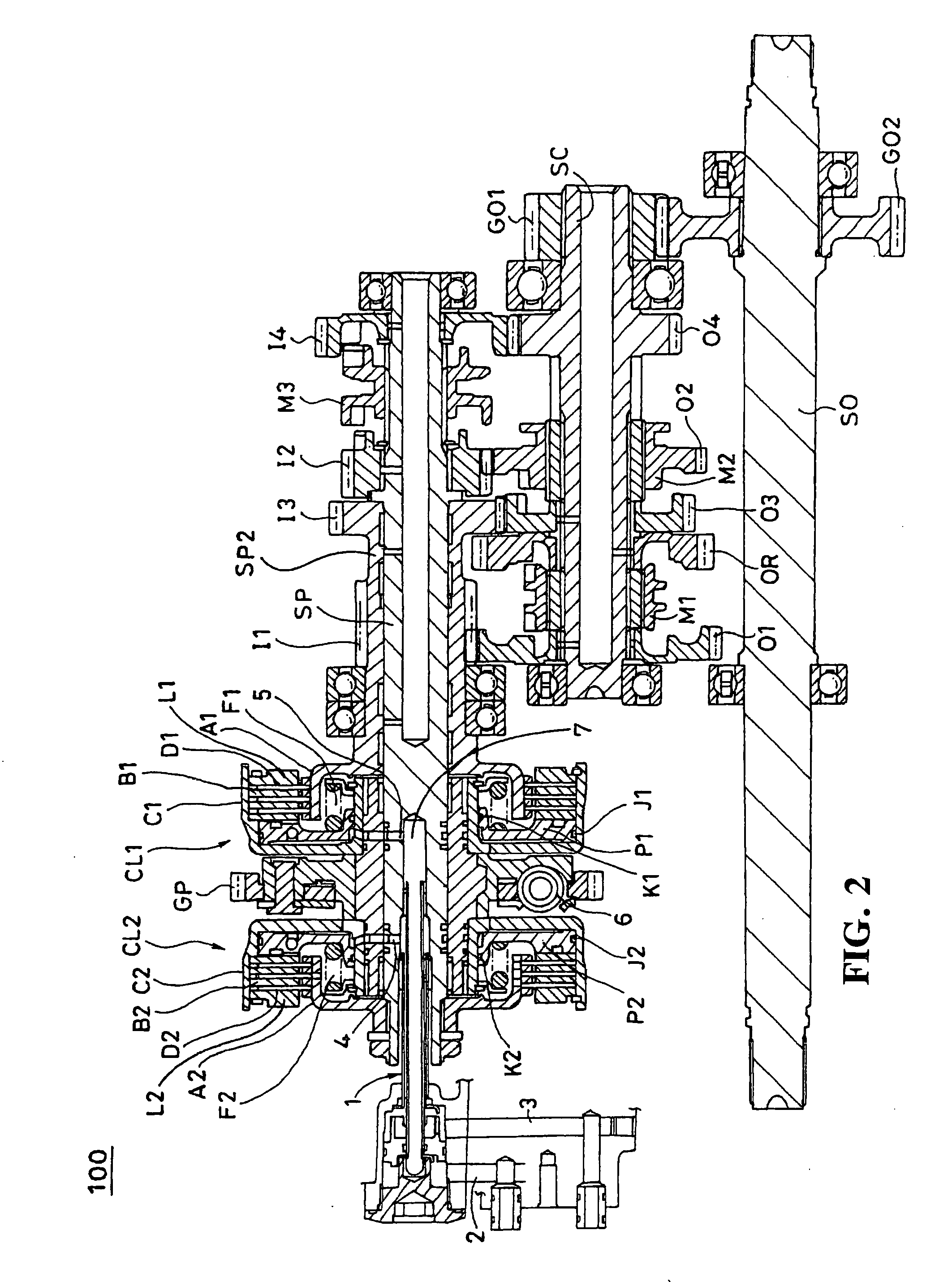
[0017] Hereinafter, the invention is explained in conjunction with drawings. FIG. 2 is an enlarged cross-sectional view of an essential part of an automatic transmission according to one embodiment of the invention. An automatic transmission 100 is a multi-stage transmission which includes four forward speeds and one backward speed. For example, the automatic transmission 100 is assembled in a four-cycle single-cylinder engine.

[0018] When a rotational speed of an engine arrives at a predetermined value (for example,2000 rpm) and a start clutch not shown in the drawing is connected, a rotational driving force of the engine is inputted to the automatic transmission 100 from a primary gear GP. The driving force which is transmitted to the primary gear GP is finally transmitted to an output shaft SO by way of a primary shaft SP which constitutes a main shaft and a transmission gear train G which includes a plurality of pairs of the gears which are mounted on the primary shaft SP and a ...


PUM


Abstract

To alleviate a shift shock of an automatic transmission when a vehicle travels at a certain vehicle speed and a speed range is changed over to a drive range from a neutral range. When a neutral range is selected by a range selection lever, a neutral determination part outputs a determination signal Nt. When a vehicle speed V is equal to or more than a vehicle speed reference value Vref, a vehicle speed determination part outputs a signal VJ2. When the vehicle speed V is less than the vehicle speed reference value Vref, a signal VJ1 is outputted. The signal VJ1 is inputted to a shift map, and a hydraulic control unit determines a speed change stage base on the vehicle speed and a throttle opening degree. When a signal VJ2 is inputted to the hydraulic control unit, the shift stage is set at the neutral range.

Description

CROSS-REFERENCE TO RELATED APPLICATIONS [0001] The present application claims priority under 35 USC 119 to Japanese Patent Application No. 2006-101886 filed on Apr. 3, 2006 the entire contents of which are hereby incorporated by reference. BACKGROUND OF THE INVENTION Field of the Invention [0002] The present invention relates to a sequential automatic transmission, and more particularly to a sequential automatic transmission which can preferably suppress an impact (shift shock) at the time of performing transmission. Description of Background Art [0003] A shift control device for an automatic transmission for a vehicle-use engine, for example, a shift control device of a plural-clutch-type transmission, is described in JP-A-2004-28117 which includes a shift manipulation mechanism for allowing a driver to give a neutral standby instruction to the transmission. When the neutral standby instruction is given from a shift manipulation mechanism, the shift control device changes over a tr...

Claims


Application Information

Patent Timeline
Patent Type & Authority Applications(United States)
IPC IPC(8): F16H61/00
CPCF16H61/0213F16H61/688Y10T477/6934Y10T477/6414Y10T477/689F16H2061/0216
Inventor TANAKA, HIROSHI
Owner HONDA MOTOR CO LTD
Why Eureka
Try Eureka