Airway adaptor

a technology of airway adaptor and adaptor, which is applied in the field of shape of airway adaptor, can solve the problems of complex structure, complex design of carbon dioxide nasal mask, and complex work such as assembling and maintenance of a plurality of parts

Active Publication Date: 2011-01-20
NIHON KOHDEN CORP
View PDF8 Cites 15 Cited by
  • Summary
  • Abstract
  • Description
  • Claims
  • Application Information

AI Technical Summary

Benefits of technology

[0011]It is therefore an object of the invention to provide an airway adaptor configured so that operations of attaching and detaching a carbon dioxide nasal mask (or a carbon dioxide face mask), to and from an expired gas guiding portion and an airway case are facilitated, the airway case is configured so as to be projected to the outside of the nasal mask (or the face mask), a hermetical configuration is formed in which introduction and discharge of the expired gas passing through the airway case can be surely performed inside the nasal mask (or the face mask) without causing air leakage to the outside thereof, and a carbon dioxide sensor can be easily attached to and detached from the airway case.

Problems solved by technology

As described above, the carbon dioxide nasal mask has a complex design, and hence works such as assembling of a plurality of parts and maintenance are required.
When the mask and the airway case are made detachable without causing air leakage, there arises a problem in that the structure is complicated.
Also in the case where the carbon dioxide sensor is attached to the airway case, the sensor must be incorporated inside the nasal mask, and there is a disadvantage in that the attaching and detaching operations are cumbersome.
Moreover, the carbon dioxide nasal mask has a special shape which is complexly designed, and hence is difficult to be produced.
Therefore, problems in production technique and cost remain to be solved.

Method used


Image

  • Airway adaptor
  • Airway adaptor
  • Airway adaptor

Examples


Embodiment Construction

[0040]Next, embodiments of the airway adaptor of the invention will be described in detail with reference to the accompanying drawings. In the figures, the identical components are denoted by the same reference numerals, and duplicated description will be omitted.

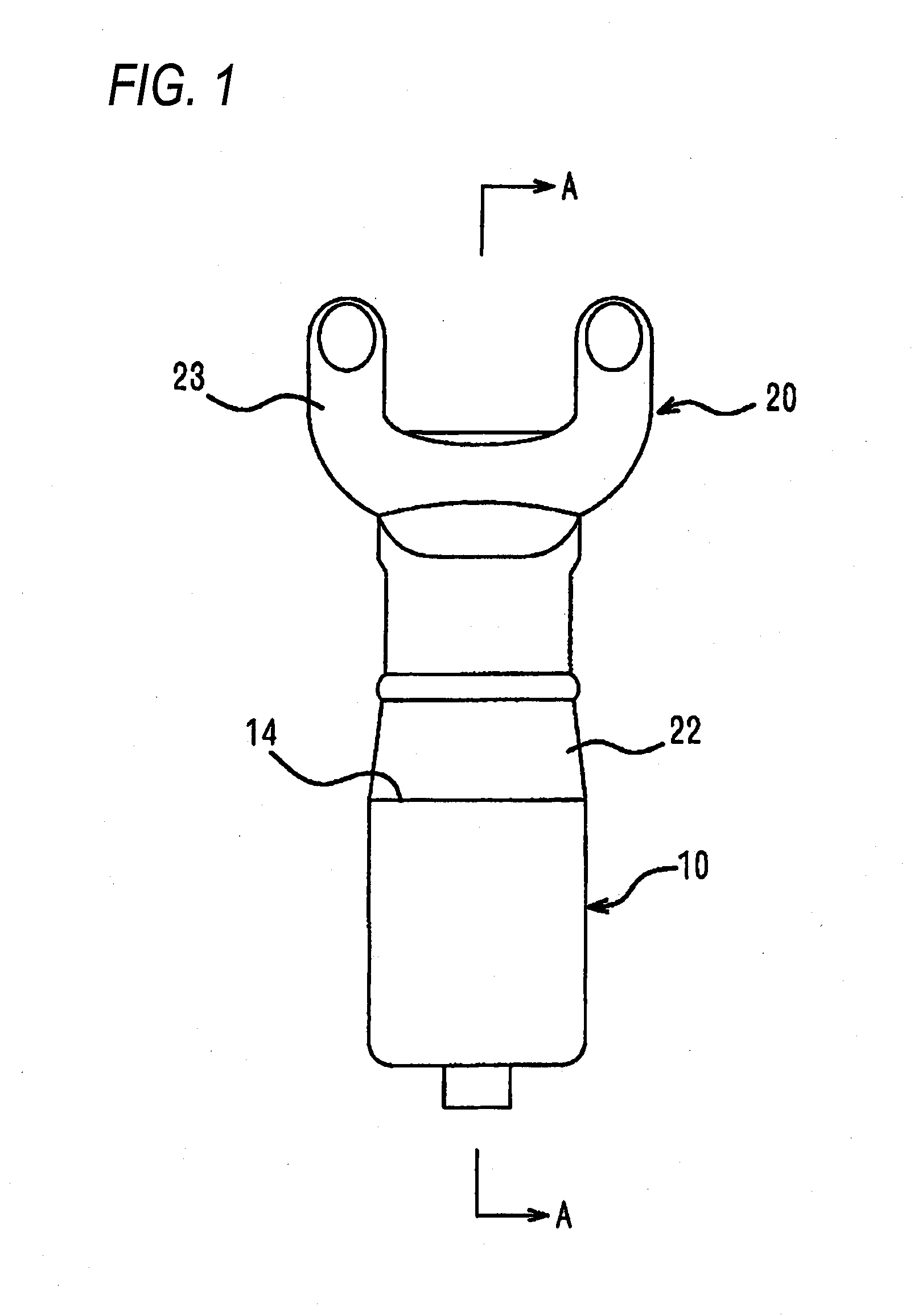
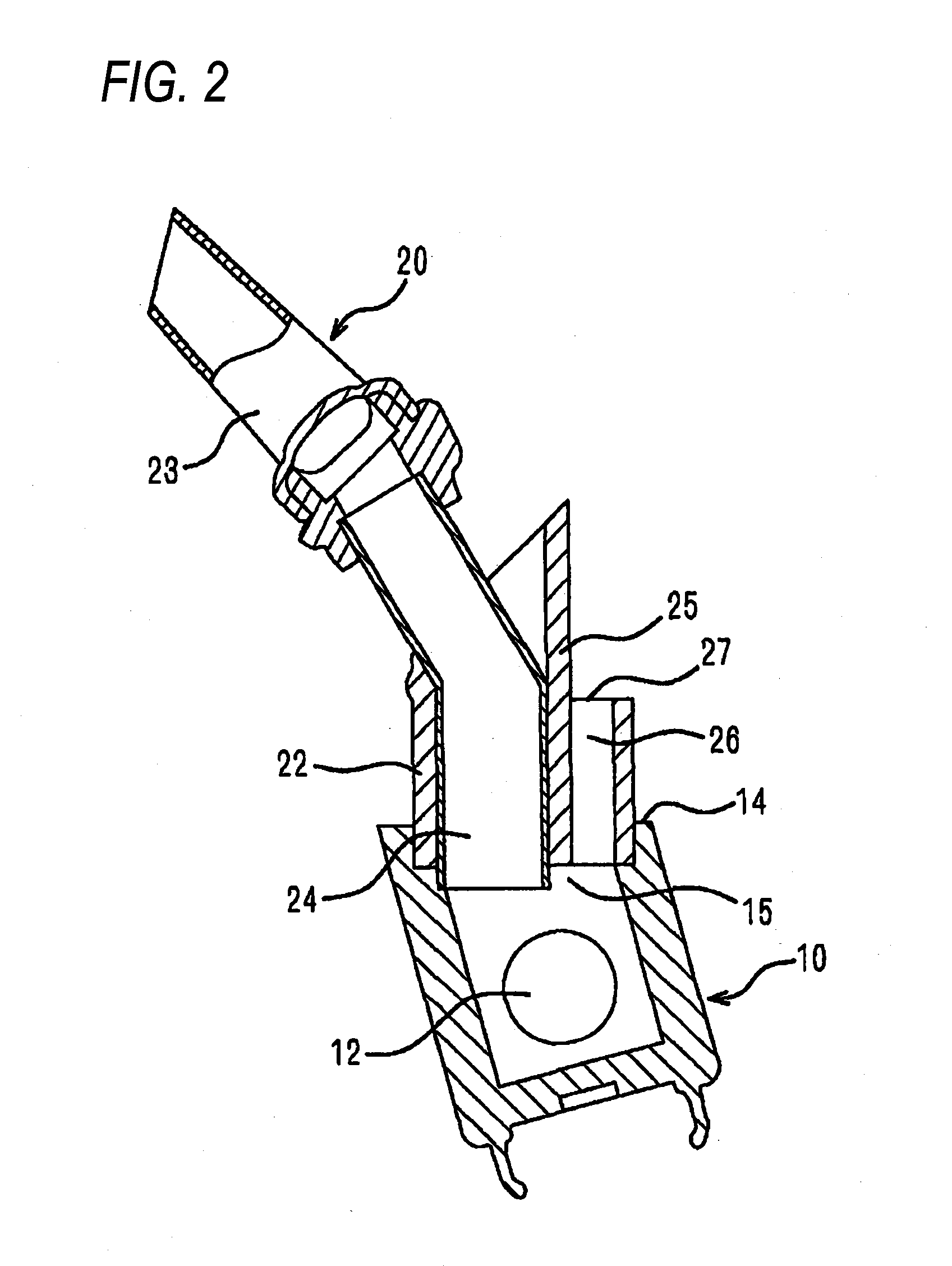
[0041]FIGS. 1 and 2 show a configuration example of the airway adaptor of the invention, FIG. 1 is a front view, and FIG. 2 is a sectional view.

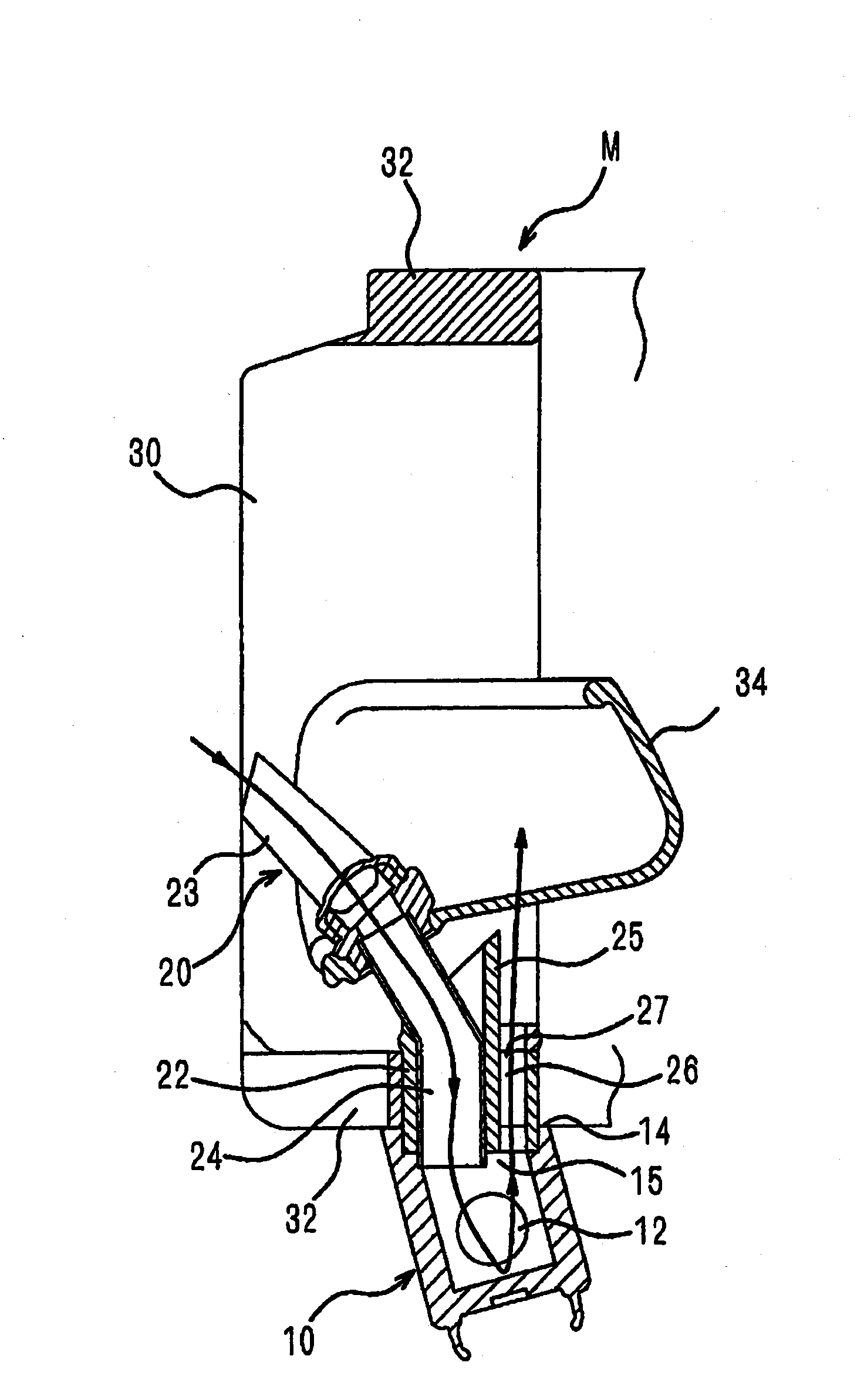
[0042]Referring to FIGS. 1 and 2, the airway adaptor of the invention is configured by an airway case 10, and an expired gas guiding portion 20 which is communicatingly connected to the airway case 10 to guidingly introduce the respiratory gas to the airway case 10. The airway case 10 and the expired gas guiding portion 20 are detachably configured.

[0043]The airway case 10 includes a joining portion 22 which is used for communicating connection to the expired gas guiding portion 20, and is configured so that transmissive windows 12 through which light is transmitted are disposed on ...


PUM


Abstract

An airway adaptor includes: an airway case; and an expired gas guiding portion which is connected to the airway case to introduce a respiratory gas to the airway case. The airway case includes: a first respiratory gas flow path in which the respiratory gas flows in a first direction; and a second respiratory gas flow path in which the respiratory gas flows in a second direction opposite to the first direction.

Description

BACKGROUND OF THE INVENTION[0001]The present invention relates to the shape of an airway adaptor for, in carbon dioxide measurement for detecting and measuring the existence, concentration, and the like of carbon dioxide in the respiratory gas expired through the nostrils or mouth of the living body, guiding the expired gas discharged through the nostrils or mouth of the living body, thereby allowing a measurement relating to carbon dioxide in the expired gas to be effectively performed. The airway adaptor is configured so that, in the case where a carbon dioxide sensor is to be attached to the airway adaptor, the operations of attaching or detaching the sensor can be performed simply and easily.[0002]For example, a related-art carbon dioxide sensor for detecting and measuring the existence, concentration, and the like of carbon dioxide in the expired gas discharged through the nostrils or mouth of the living body is configured in the following manner (see JP-A-2003-315264). An airw...

Claims


Application Information

Patent Timeline
Patent Type & Authority Applications(United States)
IPC IPC(8): A61B5/097
CPCA61B5/0836A61B5/097A61B5/682A61B5/6819A61B5/6803A61B5/082
Inventor YAMAMORI, SHINJI
Owner NIHON KOHDEN CORP
Why Eureka
Try Eureka