Diagnosable hall sensor

Inactive Publication Date: 2011-01-27
ZF FRIEDRICHSHAFEN AG
View PDF4 Cites 13 Cited by
  • Summary
  • Abstract
  • Description
  • Claims
  • Application Information

AI Technical Summary

Benefits of technology

[0010]Based on this background, it is the task of the present invention to create a diagnosable sensor device with a Hall probe, or a method for the functional diagnosis of a Hall sensor device, were a comprehensive diagnosis of the sensor device can be executed. In particular, the invention makes it possible to execute the diagnosis of the Hall senso

Problems solved by technology

Basically, there is also a risk with the Hall sensor of a failure of the sensor component, for instance due to an electronic defect.
It is also possible that the measured signal is distorted, for instance due to different operating temperatures, interfering, external magnetic fields, and mechanical stress which is transferred to the Hall sensor such that its sensitivity or characteristics, respectively, can change.
If a standard Hall sensor component fails due to such a defect, or distortions of the signal from the Hall sensor are created due to be described conditions, the problem often exists that the functionality of the Hall sensor component cannot be tested

Method used


Image

  • Diagnosable hall sensor
  • Diagnosable hall sensor
  • Diagnosable hall sensor

Examples


Embodiment Construction

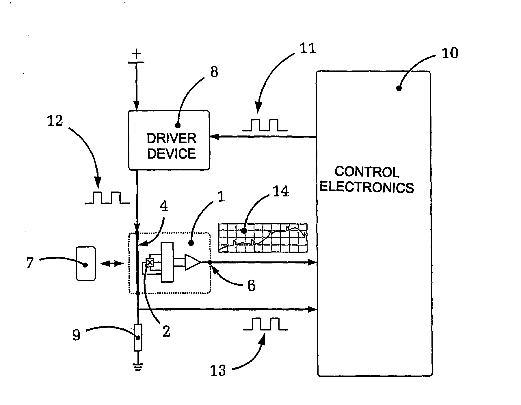
[0046]FIG. 1 shows, in a highly schematically represented circuit, the sensor device 1 of a measuring device in accordance with an embodiment of the present invention,

[0047]Initially, the Hall probe 2 can be seen, with its four edges being connected in a common way with an electronic supply and analysis circuit 3. Hereby, the necessary current can be supplied to the Hall probe 2 to create the Hall effect, and when magnetic fields become present at the edges of the Hall probe 2, which run in parallel to the feed current, the corresponding Hall voltage can be detected and registered.

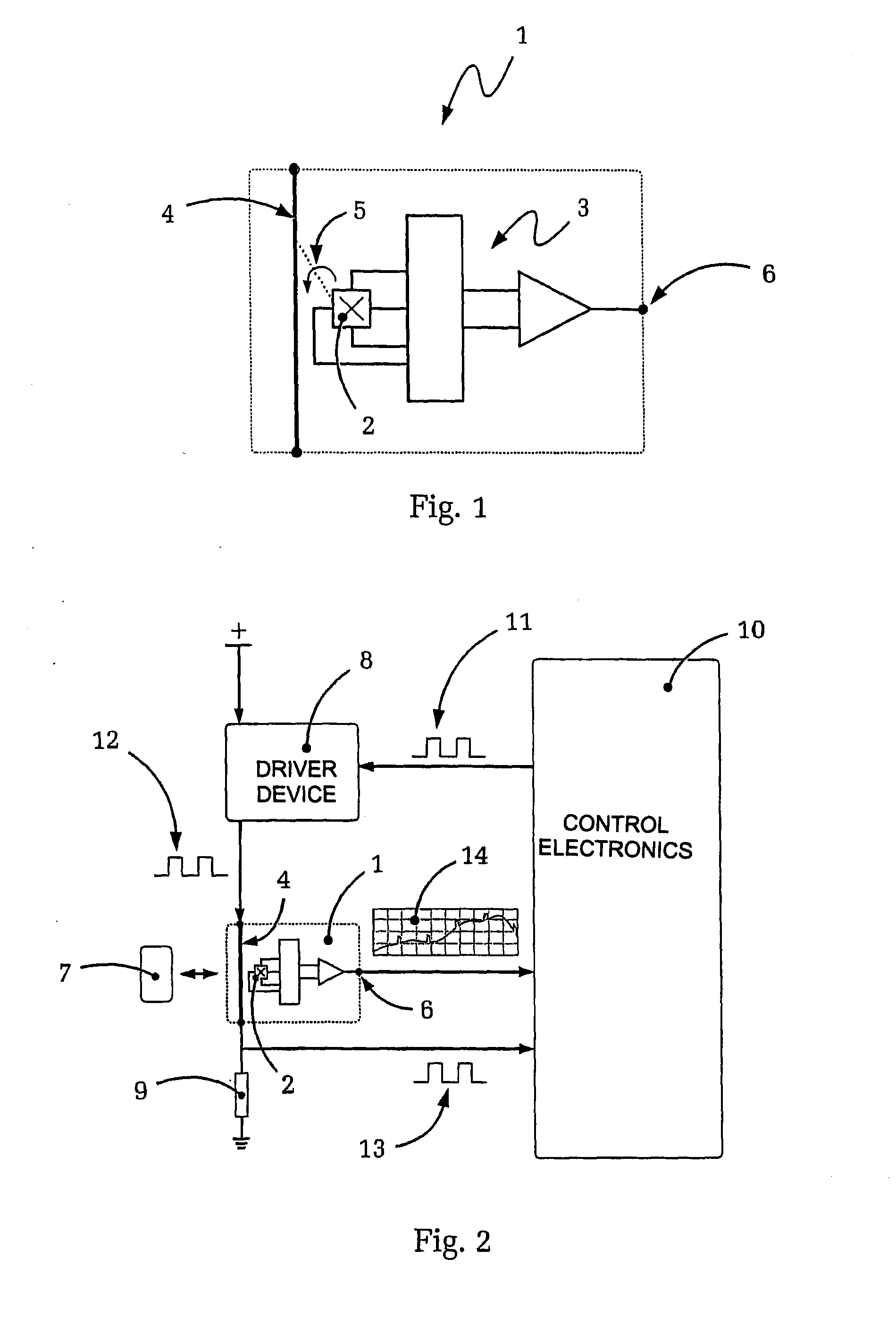
[0048]The presented sensor devise 1 comprises a diagnosis conductor 4, which is galvanically isolated from the Hall probe 2 and fed by a driver device 8 (not shown in FIG. 1, compare to FIG. 2) in a way such that certain electric diagnosis current flows in the diagnosis conductor 4.

[0049]The diagnosis current which flows through the diagnosis conductor 4 enables the creation of a magnetic field 5 around th...


PUM


Abstract

A measuring device for determining the strength of magnet fields using a Hall probe and a method for evaluating the function of a Hall sensor. The measuring device comprises a sensor having a Hall probe and an electric diagnosis conductor which is galvanically isolated from the Hall probe. The measuring device being able to continually monitor the sensor. In particular, the sensor can not only be checked qualitatively in regard to function or failure, but also quantitatively in regard to correct calibration such that, if necessary, an immediate correction or re-calibration of the sensor can be performed. In particular, measuring errors for instance, due to a temperature drift or because of mechanical stress of the sensor, can easily be eliminated.

Description

[0001]This application is a National Stage completion of PCT / DE2009 / 050012 filed Apr. 2, 2009, which claims priority from German patent application serial no. 10 2008 000 943.1 filed Apr. 2, 2008.FIELD OF THE INVENTION[0002]The invention relates to a measuring device for determining the position of a sensor device with a Hall probe.BACKGROUND OF THE INVENTION[0003]Hall probes are known in the state-of-the-art. Generally, Hall probes comprise of a conducting sensor surface through which a feed current flows. If a magnetic field is now alternating with the sensor surface through which the current flows, a deviation of the charge carriers takes place, caused by the Lorentz force on the moving electrical charge carriers in the sensor surface, transversal to their direction of movement. Hereby, and the electric field, as well as a measurable electric voltage is created between the two edges on the sides of the sensor surface.[0004]This voltage, known as the Hall voltage, is in proportion...

Claims


Application Information

Patent Timeline
IPC IPC(8): G01R33/07
CPCG01R33/07G01R15/202G01R33/06
Inventor PEUKERT, ANDREASKLIEMANNEL, WOLFGANG
Owner ZF FRIEDRICHSHAFEN AG
Why Eureka
Try Eureka