Printed Compound Loop Antenna

a compound loop antenna and antenna technology, applied in the direction of loop antennas with ferromagnetic cores, resonant antennas, independent non-interacting antenna combinations, etc., can solve the problems of low received power than would otherwise be possible, small loop antennas cannot be used in practice, and are not typically suitable for transmitters. , to achieve the effect of reducing q, reducing q, and increasing radiation intensity/power/gain

Active Publication Date: 2011-01-27
DOCKON
View PDF33 Cites 34 Cited by
  • Summary
  • Abstract
  • Description
  • Claims
  • Application Information

AI Technical Summary

Benefits of technology

The present invention is about improving printed or single-sided compound field antennas. Specifically, it focuses on compound loop antennas that have coplanar electric field radiators and magnetic loops with electric fields orthogonal to magnetic fields. These improvements result in higher bandwidth, greater radiation intensity/power/gain, and greater efficiency.

Problems solved by technology

The technical problem addressed in this patent text is the need for a compound antenna that cancels reactive power and improve the real power transmission properties of the antenna. The solution involves designing a compound antenna that combines the electric and magnetic fields in a way that cancels reactive power. The challenge is to create a compact antenna that can be easily implemented and optimized for use in wireless communication systems. The text also describes the effect of energy stored in the near field of an antenna on the performance of the antenna.

Method used


Image

  • Printed Compound Loop Antenna
  • Printed Compound Loop Antenna
  • Printed Compound Loop Antenna

Examples


Embodiment Construction

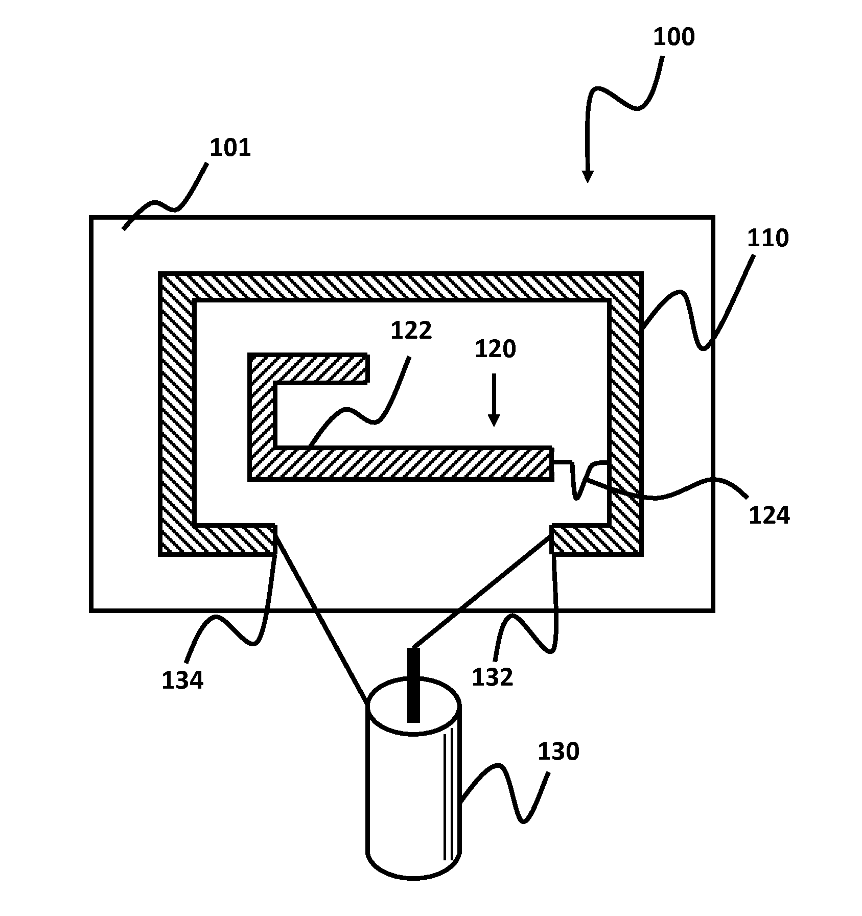
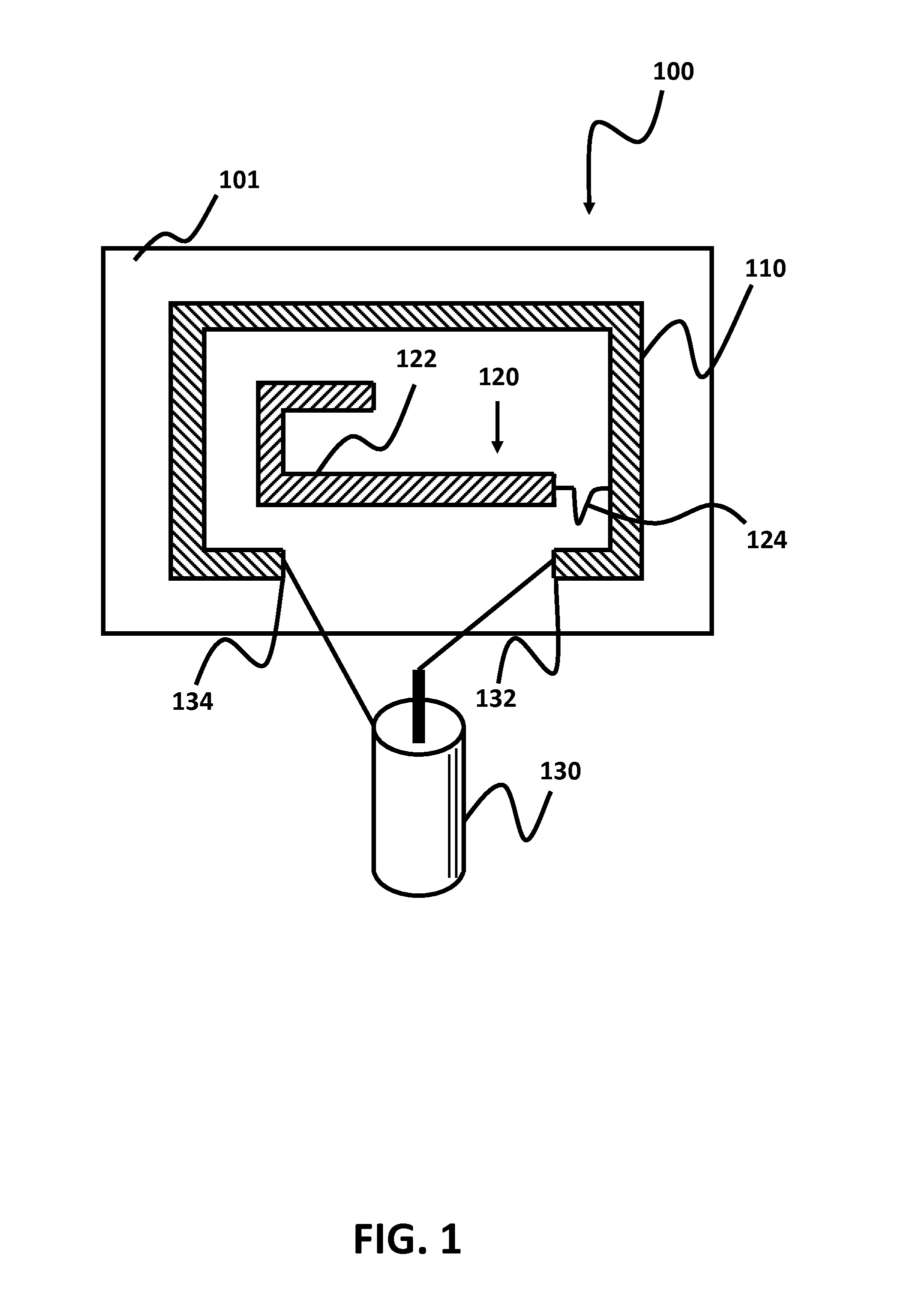
Embodiments provide an single-sided, compound loop (CPL) antenna, capable of operating in both transmit and receive modes and enabling greater performance than known loop antennas. The two primary components of a CPL antenna are a magnetic loop that generates a magnetic field (H field) and an electric field radiator that emits an electric field (E field).

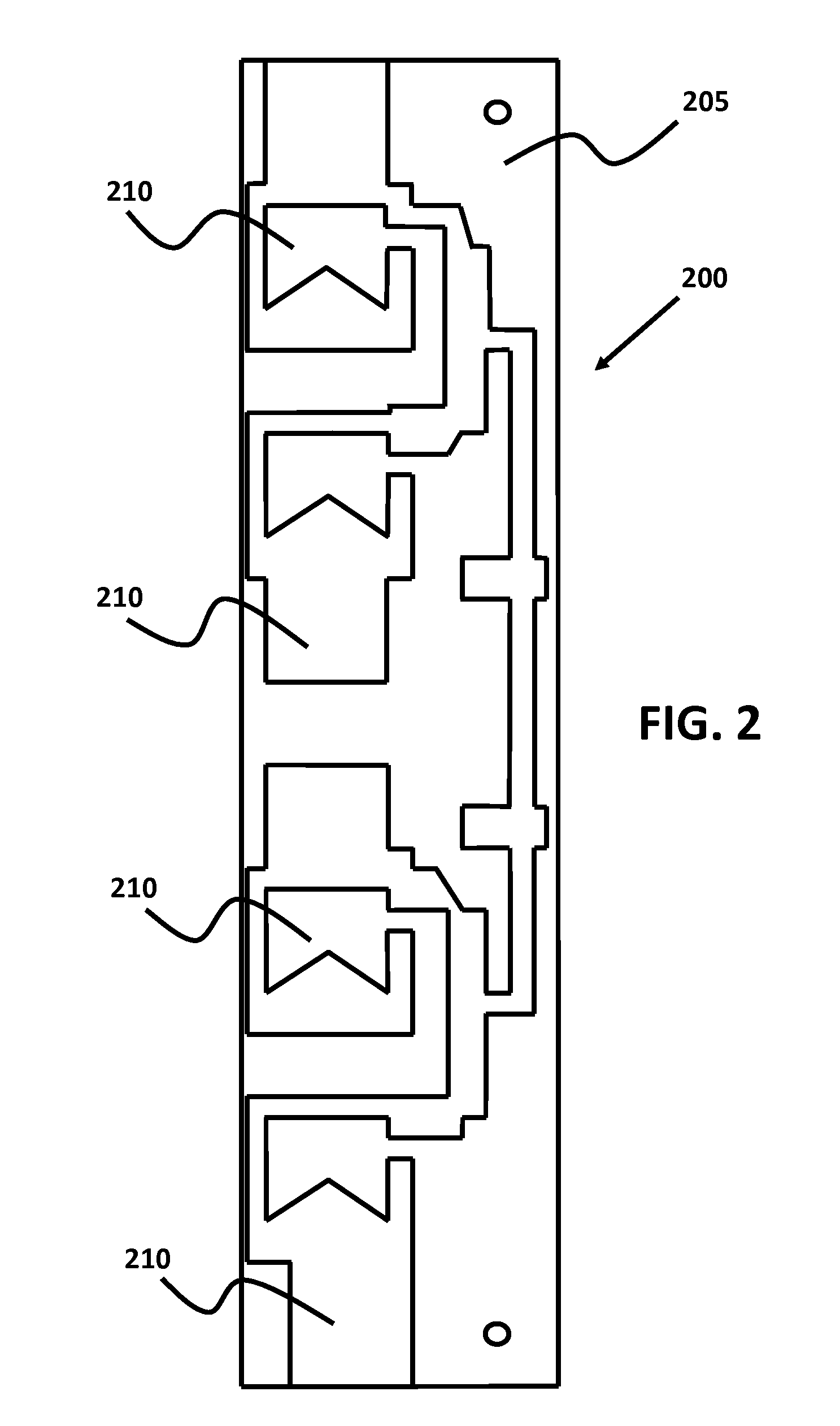
The electric field radiator may be physically located either inside the loop or outside the loop. For example, FIG. 1 shows an embodiment of a single CPL antenna element with the electric field radiator located on the inside of the loop coupled by an electrical trace, while FIGS. 3A and 3B show two embodiments of a single CPL antenna element with the electric field radiator located on the outside of the loop. FIG. 3A, as further described below, includes a phase tracker for broadband applications, while FIG. 3B does not include the phase tracker and is more suitable for less wideband applications. FIGS. 4A, 4B and 4C illustrate othe...


PUM


Abstract

The present invention relates to printed or single-sided compound field antennas. The single-sided compound loop antennas have coplanar electric field radiators and magnetic loops with electric fields orthogonal to magnetic fields that achieve performance benefits in higher bandwidth (lower Q), greater radiation intensity/power/gain, and greater efficiency.

Description


Claims


Application Information

Patent Timeline
Owner DOCKON
Why Eureka
Try Eureka