Unlock instant, AI-driven research and patent intelligence for your innovation.

Optical apparatus having optical Anti-shake function

Inactive Publication Date: 2011-01-27
CANON KK
View PDF8 Cites 5 Cited by
  • Summary
  • Abstract
  • Description
  • Claims
  • Application Information

AI Technical Summary

Benefits of technology

The present invention provides a small-sized optical apparatus capable of well reducing an image blur caused by a shake in a high-frequency range.
An optical apparatus as one aspect of the present invention includes an optical system, a shake detector configured to detect a shake, an electro-optic element constituting a part of the optical system and configured to change a refractive-index distribution by an electro-optic effect in accordance with an applied voltage, a drive unit configured to apply a voltage to the electro-optic element so as to reduce an image blur detected by the shake detector, and an anti-shake unit configured separately from the electro-optic element to reduce the image blur detected by the shake detector.

Problems solved by technology

However, in the optical anti-shake apparatus disclosed in Japanese Patent Laid-open Nos. 2004-61910 and H2-168223, because a mechanical drive of the lens or the variable angle prism is necessary, it is difficult to sufficiently correct the image blur of a frequency beyond the frequency range of the hand shake.

Method used


Image

  • Optical apparatus having optical Anti-shake function
  • Optical apparatus having optical Anti-shake function
  • Optical apparatus having optical Anti-shake function

Examples


embodiment 1

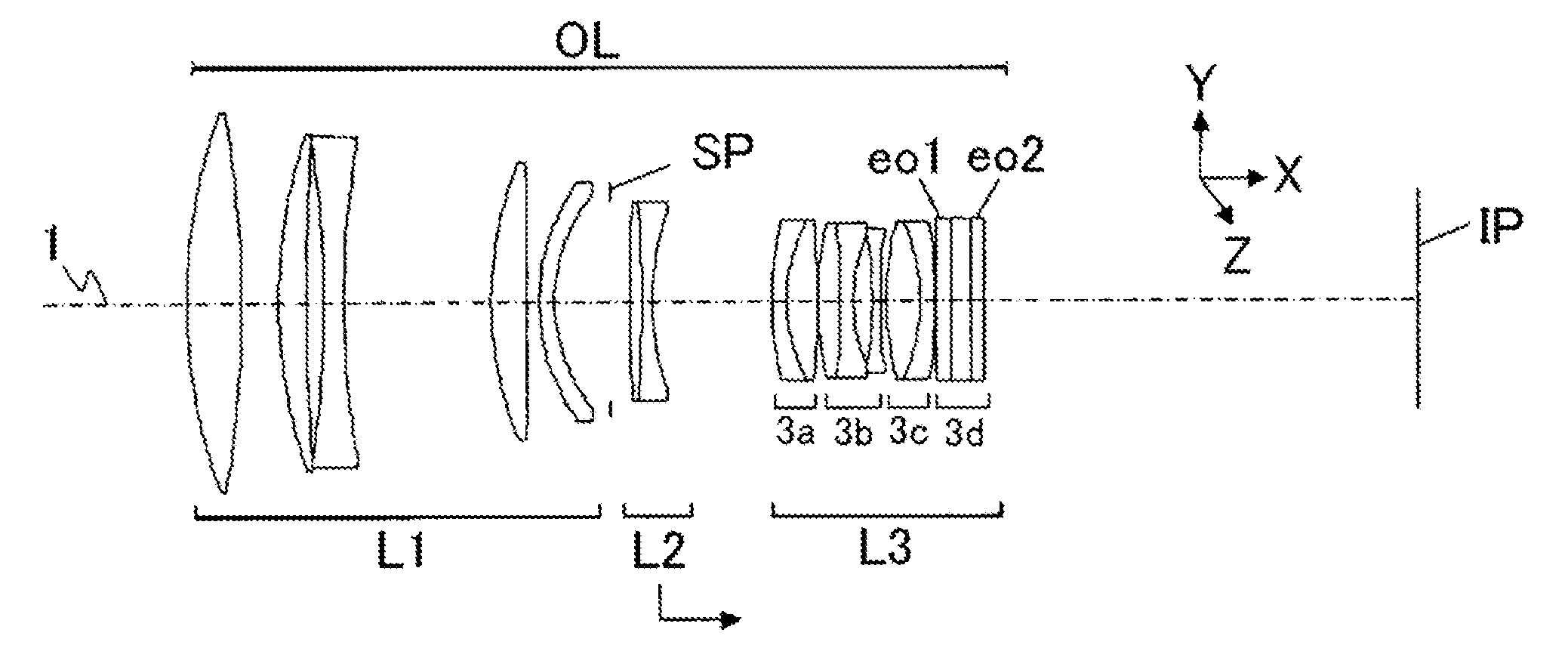
In Embodiment 1 described with reference to FIG. 2, an optical system OL is a telephoto lens having a focal length of 294 mm. In the optical system OL, a second lens unit L2 is a focus lens unit, which moves to an image side to perform a focus operation when an object distance decreases. A third lens unit L3 includes a first lens component 3a and a third lens component 3c which are fixed (do not move) in performing a focus operation and an anti-shake operation, and an anti-shake lens unit 3b which shifts in a direction orthogonal to an optical axis 1 in performing the anti-shake operation. The third lens unit L3 includes an anti-shake electro-optic element unit 3d which is constituted by electro-optic elements eo1 and eo2.

The anti-shake lens unit 3b is mainly used for reducing or correcting an image blur caused by a shake in a low-frequency range. The anti-shake electro-optic element unit 3d is mainly used for reducing an image blur caused by a shake in a high-frequency range. Thus,...

embodiment 2

In Embodiment 2 described with reference to FIG. 5, an optical system OL is a telephoto lens having a focal length of 294 mm. The optical system OL, basically, has the same configuration as that of the optical system of Embodiment 1. A third lens unit L3 includes an anti-shake electro-optic element unit 3d containing electro-optic elements eo1 and eo2.

FIG. 6A, as described above, illustrates a lateral aberration diagram of the optical system OL of the present embodiment in a reference state where there is no image blur. FIGS. 6B and 6C illustrate lateral aberration diagrams when the anti-shake operation is performed by the anti-shake electro-optic element unit 3d while a shake (a rotational shake of 0.03 degree) causing image blurs of y=−0.1 mm in a Y direction and z=−0.1 mm in a Z direction respectively is generated in the optical apparatus.

Also in the present embodiment, the KTN crystal is used as electro-optic elements eo1 and eo2 of the anti-shake electro-optic element unit 3d. ...

embodiment 3

In Embodiment 3 described with reference to FIG. 8, an optical system OL is a zoom lens having a focal length which changes between 6 mm and 96.5 mm. The optical system OL, in order from an object side, includes a first lens unit L1 having a positive refractive power, a second lens unit L2 having a negative refractive power, a third lens unit L3 having a positive refractive power, and a fourth lens unit L4 having a positive refractive power.

As indicated by arrows in FIG. 8, in a zoom operation from a wide-angle end to a telephoto end, the first lens unit L1 moves with a convex trajectory to an image side, and the second lens unit L2 moves to the image side. The third lens unit L3 moves to an object side, and the fourth lens unit L4 moves with a convex trajectory to the object side.

The fourth lens unit L4 is a focus lens unit, which moves to the object side for performing a focus operation when an object distance becomes short.

The third lens unit L3 includes an anti-shake lens unit 3...


PUM


Abstract

An optical apparatus of the present invention includes shake detectors 25p and 25y which detect a shake, electro-optic elements eo1 and eo2 which constitute a part of the optical system and change refractive-index distributions by an electro-optic effect in accordance with an applied voltage, and a drive unit 23 which applies a voltage to the electro-optic element so as to reduce an image blur detected by the shake detectors.

Description

BACKGROUND OF THE INVENTION1. Field of the InventionThe present invention relates to an optical apparatus having an optical anti-shake function such as a camera, an interchangeable lens, or a telescope, and more particularly to an optical apparatus which realizes the optical anti-shake function using an electro-optic element.2. Description of the Related ArtIn order to reduce an image blur caused by a shake such as a hand shake, previously, an optical anti-shake apparatus which deflects luminous flux heading to an image plane by shifting a lens or changing an apex angle of a variable angle prism has been proposed (see Japanese Patent Laid-open Nos. 2004-61910 and H2-168223). Furthermore, an optical anti-shake apparatus which uses a liquid crystal inclusion element in which a refractive-index variable liquid crystal is included in a wedge-shaped space and a voltage applied to the liquid crystal inclusion element is controlled to uniformly changes the refractive index of the liquid cr...

Claims


Application Information

Patent Timeline
IPC IPC(8): G03B17/00
CPCG02B27/646G03B5/00G03B2205/0007H04N5/23209G03B2205/0053H04N5/23258H04N5/23296H04N5/2628H04N5/23248H04N23/663H04N23/68H04N23/6812H04N23/69
Inventor MAETAKI, SATOSHI
Owner CANON KK