
System and Method for Minimizing the Side Effects of Refractive Corrections Using Line or Dot Cuts for Incisions

a refractive correction and line or dot technology, applied in the field of system and method for minimizing the side effects of refractive correction using line or dot cuts for incisions, can solve the problems of introducing uncertainties that may compromise the final refractive outcome, annoying side effects in the night, and annoying side effects, so as to achieve the effect of weakening the biomechanical stress distribution

Inactive Publication Date: 2011-01-27
TECHNOLAS PERFECT VISION
View PDF22 Cites 16 Cited by
  • Summary
  • Abstract
  • Description
  • Claims
  • Application Information

AI Technical Summary

Benefits of technology

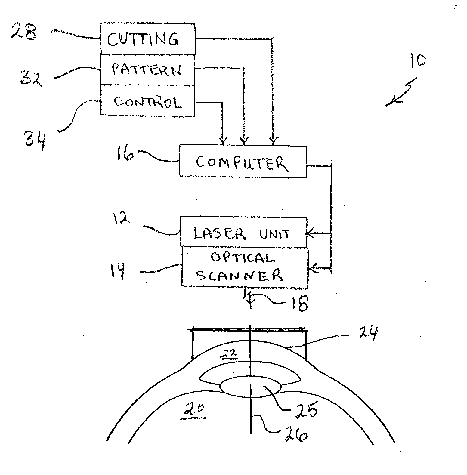
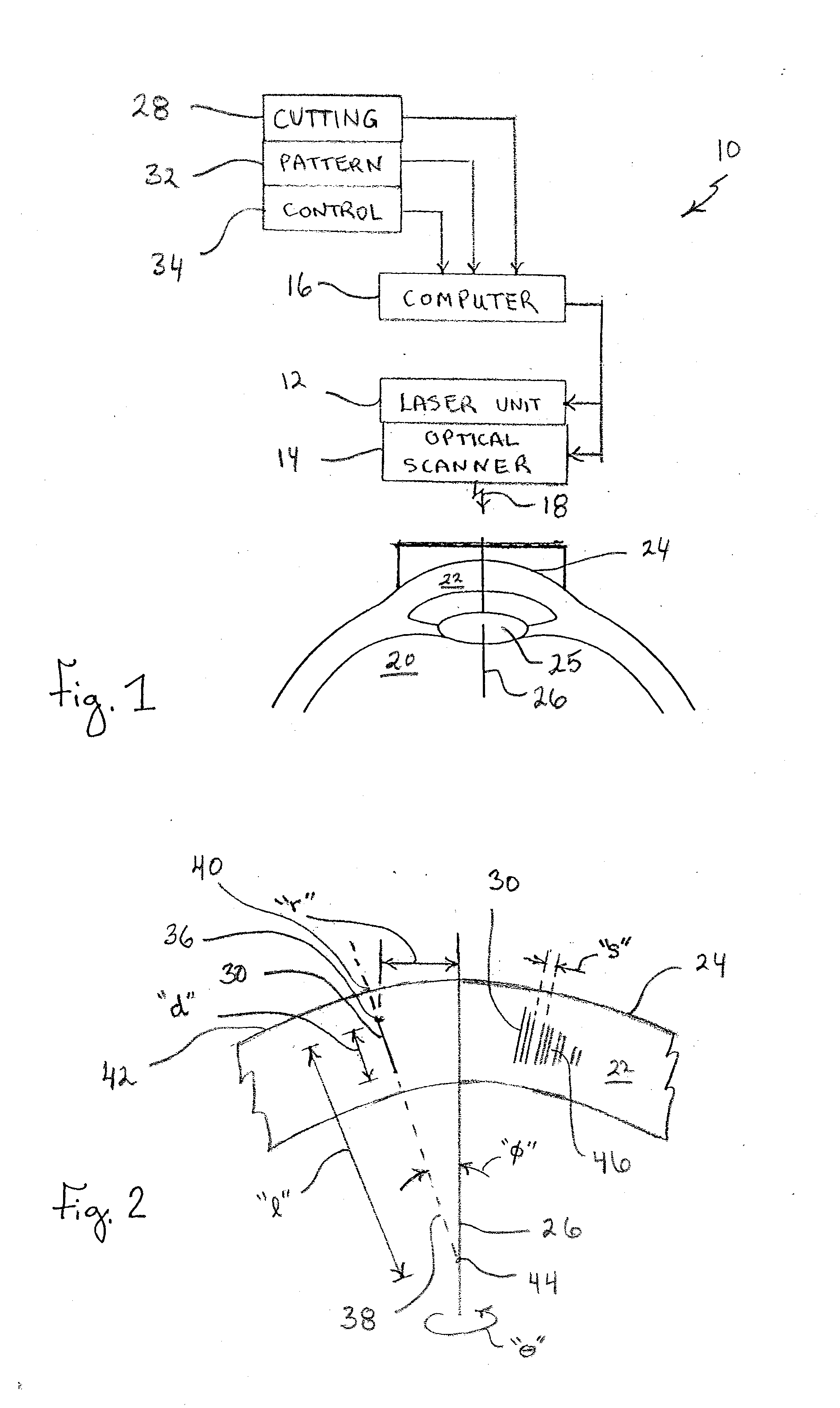
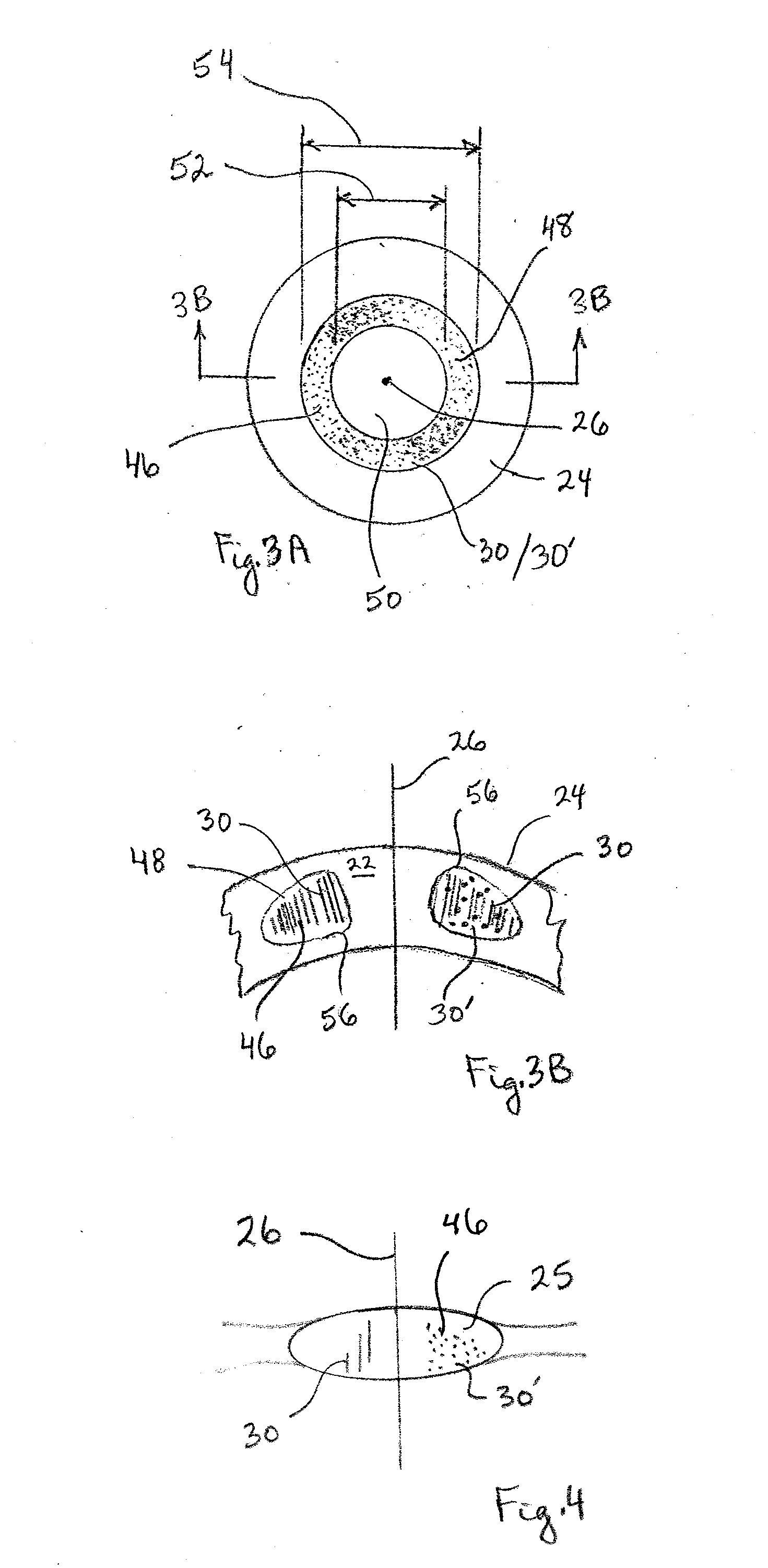
[0007]In accordance with the present invention, a system for performing laser refractive surgery on either the stroma or lens of an eye includes a laser unit, an optical scanner unit and a computer. In combination, the laser unit and the optical scanner unit are computer-controlled to create a pattern of straight line cuts inside the tissue (lens or stroma) of the eye. The purpose here is two-fold. For one, the cuts are intended to weaken biomechanical stress distributions in the tissue in a manner that provides for a desired refractive vision correction. For another, the cuts are statistically distributed in the pattern to become visually illusive.

Problems solved by technology

In these LASIK cases, however, there is still the possibility of introducing uncertainties that may compromise the final refractive outcome.
It can happen in a small number of cases, however, that these incisions may introduce annoying side-effects in night-vision (e.g. halos, ring-patterns around bright light sources).
Further, annoying side-effects may result inherently due to the multifocality of the reshaped cornea.
Like refractive corrections for the stroma, however, cuts into the lens of an eye may also introduce annoying side effects.

Method used


Image

  • System and Method for Minimizing the Side Effects of Refractive Corrections Using Line or Dot Cuts for Incisions
  • System and Method for Minimizing the Side Effects of Refractive Corrections Using Line or Dot Cuts for Incisions
  • System and Method for Minimizing the Side Effects of Refractive Corrections Using Line or Dot Cuts for Incisions

Examples


Embodiment Construction

[0021]Referring initially to FIG. 1, a system for performing refractive surgery on an eye (transparent material) is shown and is generally designated 10. As shown, the system 10 essentially includes a laser unit 12, an optical scanner 14 and a computer 16. In combination, the computer 16 is used to control both the laser unit 12 and the optical scanner 14 to respectively generate and direct a pulsed laser beam 18. The laser beam 18 is then used to perform refractive surgery on an eye 20. More specifically, the system 10 directs and focuses the laser beam 18 into the stromal tissue 22 of the cornea 24 of an eye 20 or into the lens 25 of the eye 20 to perform this surgery.

[0022]For purposes of control, the laser beam 18 is moved relative to a reference axis 26 that is defined by the eye 20. This reference axis 26 can be either a visual axis, an optical axis, a line-of-sight axis, a pupillary axis or a compromise axis. For operational purposes, the laser beam 18 can have any characteri...


PUM


Abstract

A system and method for performing refractive surgery in an eye requires creating a plurality of cuts in the stroma or the lens that are randomly positioned relative to a reference axis. The geometry for each cut is unique and includes a start point in the stroma that is identified by a distance “r” from the axis, and an azimuthal angle “θ” that is measured around the axis. A computer provides concerted control for a laser unit and an optical scanner to randomly vary the start point for each cut, to create a pattern of cuts that will implement the desired refractive surgery, yet be visually illusive.

Description

[0001]This application is a continuation-in-part of application Ser. No. 12 / 349,257 filed Jan. 6, 2009, which is currently pending. The contents of application Ser. No. 12 / 349,257 are incorporated herein by reference.FIELD OF THE INVENTION[0002]The present invention pertains generally to systems and methods that are useful for altering the refractive properties of a transparent material. More specifically, the present invention pertains to systems and methods that weaken tissue on an eye with a laser beam, to correct vision defects of the eye. The present invention is particularly, but not exclusively, useful as a system and method for weakening eye tissue with laser incisions constituting linear or dot cuts that are statistically distributed (i.e., pseudo-random), to thereby become visually elusive for minimizing adverse visual side effects that might otherwise be introduced.BACKGROUND OF THE INVENTION[0003]PresbyLASIK is an excimer laser based method that is used to achieve a mult...

Claims


Application Information

Patent Timeline
IPC IPC(8): A61F9/008
CPCA61F9/008A61F9/00827A61F9/00838A61F2009/00897A61F2009/0087A61F2009/00872A61F2009/00857
Inventor BILLE, JOSEF F.HOHLA, KRISTIANLOESEL, FRIEDER
Owner TECHNOLAS PERFECT VISION
Learn More