Garden shears

a shear and garden technology, applied in the field of garden shears, can solve the problems of increasing static friction, affecting the operation, and affecting the operation, and achieve the effect of reducing the stactic friction

Inactive Publication Date: 2011-02-03
HO CHENG GARDEN TOOLS
View PDF64 Cites 19 Cited by
  • Summary
  • Abstract
  • Description
  • Claims
  • Application Information

AI Technical Summary

Benefits of technology

The slidable member slides along the first slot of the gripping handle and utilizes the tongue to push against the concave region of the engaging member in the containment space. When the slidable member is pushed forward it pushes the engaging member against the engaging slot of the moveable blade; and with the interactive relationship between the slidable member and the engagement set, the slidable member is able to slide along a straight line to reduce stactic friction.

Problems solved by technology

The pawl 53 swings around the axle aperture 531 and the pushing surface 532 slides in an arc-shaped path, which increases the static friction and makes the engagement movement more difficult.
However, in operation, if the pawl 53 is too loose, it may be pushed by the torsion spring 54 and move into the locking ratchet 62 of the lower gripping handle 60, which can cause difficulties during operation.

Method used


Image

  • Garden shears
  • Garden shears
  • Garden shears

Examples


Embodiment Construction

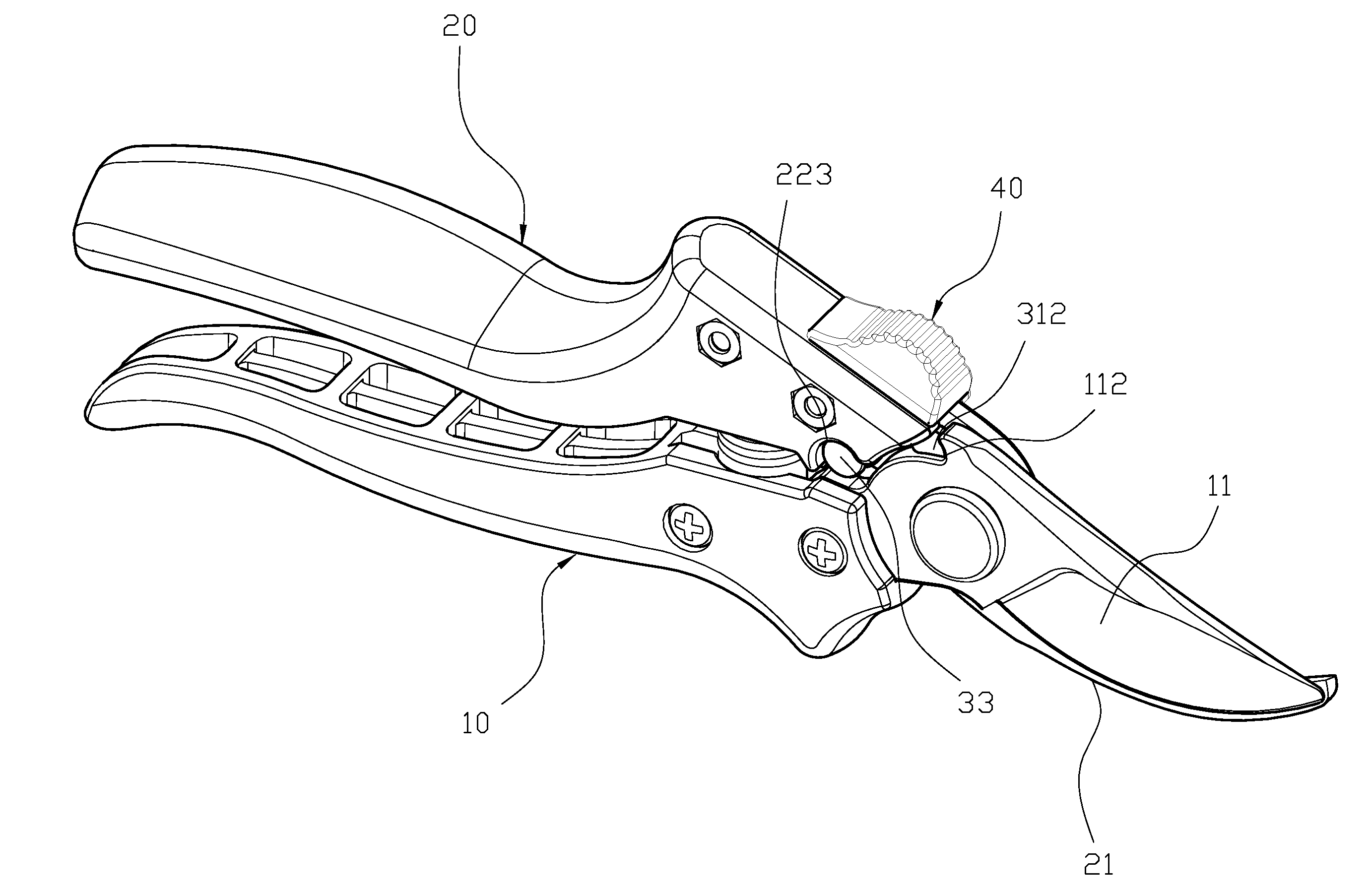
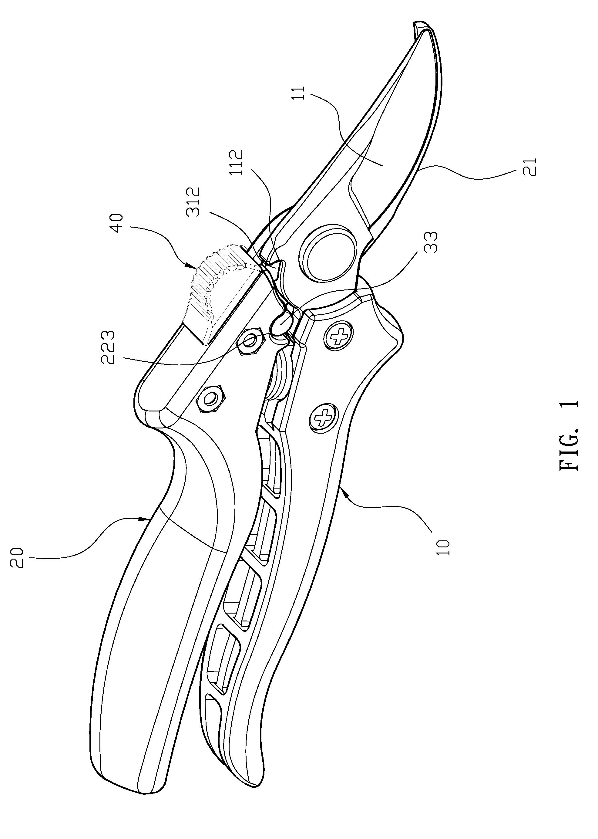
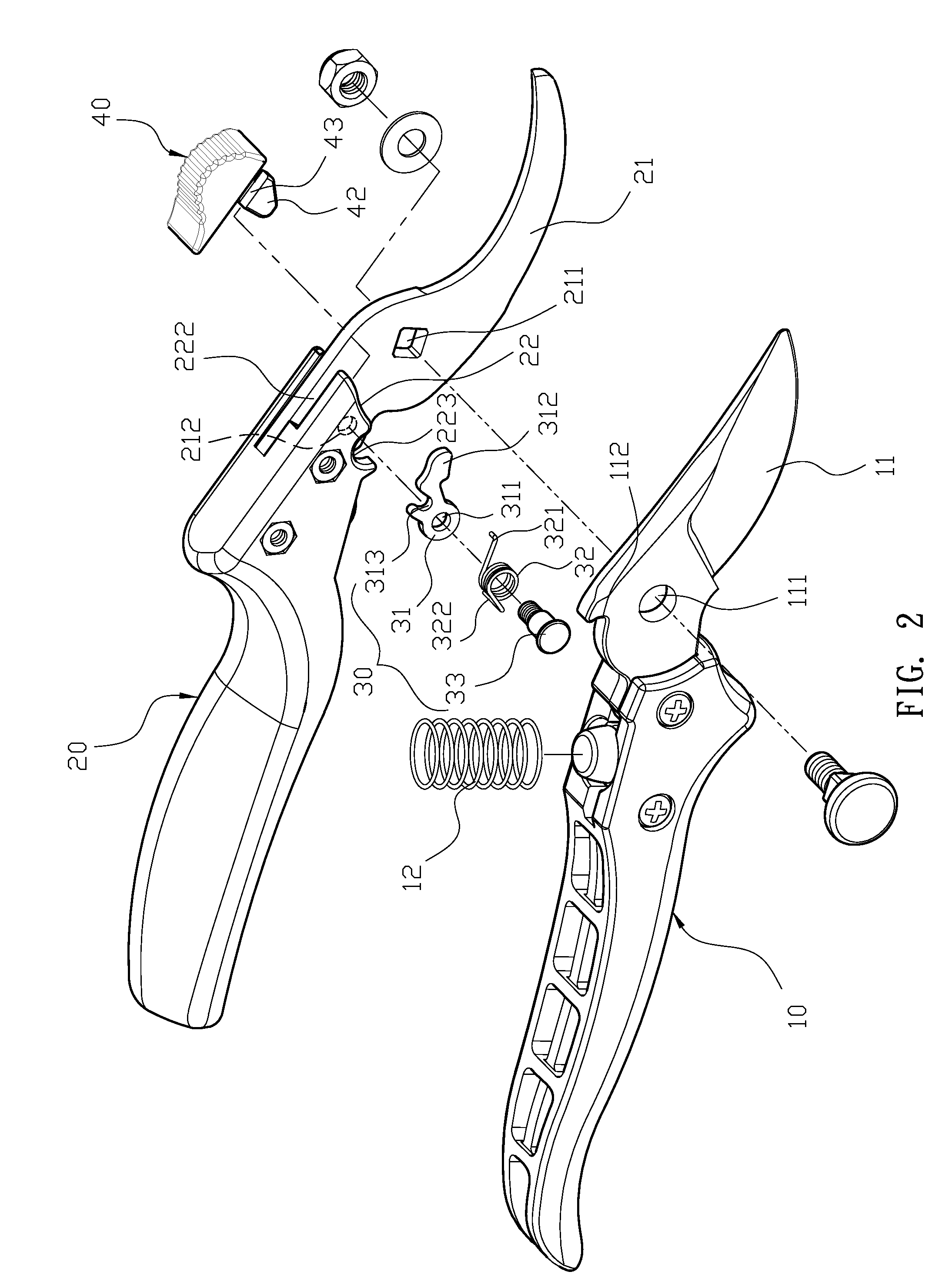
Please refer FIG. 1, FIG. 2 and FIG. 3. An embodiment garden shears comprises: a pressing handle 10, a gripping handle 20, an engagement set 30 and a slidable member 40. The pressing handle 10 is connected to a moveable blade 11 and the moveable blade 11 includes a hook-shaped engaging slot 112 on the moveable blade 11 close to the outer edge of a first aperture 111. A fixed blade 21 of the gripping handle 20 utilizes a second aperture 211 that is pivoted to the first aperture 111. A containment space 22 is formed by the junction of the gripping handle 20 and a side of the fixed blade 21. The containment space 22 has a narrowed portion 221 and a first slot 222 adjacent to the fixed blade 21. The containment space 22 has an arc-shaped opening 223, and the fixed blade 21 has a positional aperture 212 at a position corresponding to the opening 223. The engagement set 30 comprises an engaging member 31, an elastic member 32 and a positioning pin 33. One end of the engaging member 31 has...


PUM


Abstract

A pressing handle is connected to a moveable blade having a hook-shaped engaging slot near the outer edge of an aperture to which a gripping handle fixed blade is pivoted. A containment space is formed by the junction of the gripping handle and a side of the fixed blade. The containment space has an arc-shaped opening, and the fixed blade has a positional aperture at a position corresponding to the opening. An end of an engaging member has an axle aperture and another end forms an engaging end, with a concave region formed between the two ends. A positioning pin passes through the engaging member and a torsion spring and is attached to the positional aperture. A push button-shaped body has a tongue at its lower end, an edge of which extends as a stop, and the tongue and the stop are both slidably mounted in the containment space.

Description

BACKGROUND OF THE INVENTION1. Field of the InventionThe present invention relates to garden shears, and, more particularly, to garden shears that utilize an interactive relationship between the slidable member and the engagement set, in which the slidable member is able to slide along a straight line to reduce static friction.2. Description of the Related ArtPrior art garden shears, as shown in FIG. 6, are composed of upper and lower gripping handles 50,60 that are pivoted together, and also includes a spring 51. The spring 51 is disposed between the upper and lower gripping handles 50,60 and is used for pushing apart the upper and lower gripping handles 50,60, thereby biasing apart a blade base 52 and a blade 61. The upper gripping handle 50 has a pawl 53 located at the pivot position, and an axle aperture 531 of the pawl 53 is jacketed with a torsion spring 54. One end of the pawl 53 has a pushing surface 532, and a tongue 533 and a stop end 534 are formed on two sides of the pawl...

Claims


Application Information

Patent Timeline
Patent Type & Authority Applications(United States)
IPC IPC(8): B26B13/00B26B13/28
CPCB26B13/16A01G3/02
Inventor HUANG, YAO-CHUNG
Owner HO CHENG GARDEN TOOLS
Why Eureka
Try Eureka