Miniature condenser microphone and fabrication method therefor

a condenser microphone and microphone technology, applied in the field of microfabricated airborne acoustic microphones, can solve the problems of inherently difficult to protect the microphone, direct affecting the sensitivity of the microphone, and difficult to manufacture, so as to reduce the manufacturing cost

Inactive Publication Date: 2006-09-28
FOR NAT RES INITIATIVES
View PDF18 Cites 13 Cited by
  • Summary
  • Abstract
  • Description
  • Claims
  • Application Information

AI Technical Summary

Benefits of technology

[0015] It is another object of the present invention to minimize the influence of stiction on the performance of said acoustical transducer.
[0018] It is yet a further object of the present invention to provide a fabrication process with a minimal number of layers and masks to reduce the fabrication cost.
[0019] It is still another object of the present invention to provide a fabrication process that will allow the mechanical coupling of two or more such acoustic transducers to realize a directional acoustic transducer.
[0021] The present invention results from the realization that, by preventing the suspension structure from controlling the movement of the diaphragm in response to an applied sound pressure, it is possible to eliminate the dependency of the microphone performance on the exact stiffness, and hence dimensional variation, of the suspension structure. Furthermore, if a suspension structure is used which has a restoring force equal to or greater than the surface contact forces in the device, problems associated with stiction can be greatly reduced. A second important realization is that an acoustic seal can be created by utilizing the electrostatic force generated between the diaphragm and fixed counter electrode during operation of the microphone, thereby improving the low-frequency performance of the microphone over other suspended diaphragm structures in the prior art. A third important realization is that by providing for a mechanical flexible connection between two or more such diaphragms, a microphone with directional response may be realized.

Problems solved by technology

A common problem with electret microphones is leakage of electrical charge from the electret, which directly affects the sensitivity of the microphone.
This problem is especially severe at elevated temperature and humidity levels.
It is inherently difficult to protect the microphone, since it must be exposed to the environment to detect an acoustic signal.
Condenser microphones do not suffer from this problem; however due to the large air gaps in devices made with traditional fabrication methods, the external DC potentials required are in the order of hundreds of Volts, which is difficult to realize in battery powered systems.
An important limiting parameter for the performance, specifically sensitivity, of micro fabricated microphones is the mechanical sensitivity of the diaphragm in the device.
In micro fabrication, it is difficult to control the intrinsic stress levels in materials, hence special attention is required to solve this problem.
There is, however, some undesirable features associated with prior art devices.
As a result, the low-frequency roll-off of microphone 210 is directly determined by these slots, the dimensions of which are difficult to control.
This problem is especially important if the diaphragm is composed of more than one material, which may induce a stress gradient by mismatch of thermal expansion in the different materials.
Unfortunately, surface forces and associated stiction is a predominant effect in micro fabrication due to the extremely smooth surfaces in the device.
A fundamental limitation on the directivity of a single pressure type microphone is that the size of the sound detecting diaphragm must be comparable to the wavelength of the sound of interest to achieve significant directivity.
For very small devices, it is difficult and costly to manufacture screen material with high enough acoustical resistance to meet the condition above.
The disadvantages of adding electronic delays are the number of external components needed to realize the functionality, and the need for finely tuned and matched microphones in the array.
A common drawback of all approaches described above is the relative bulkiness of the devices, which does not lend itself well to miniaturization due to fundamental limitations in the underlying physics upon which these devices are based.
Unfortunately, the micro fabrication of a single diaphragm with these properties is difficult and problems with stress and stress gradients in the diaphragm material, leading to intrinsic curling and deflection, complicates the matter in a similar fashion as described earlier.

Method used


Image

  • Miniature condenser microphone and fabrication method therefor
  • Miniature condenser microphone and fabrication method therefor
  • Miniature condenser microphone and fabrication method therefor

Examples


Embodiment Construction

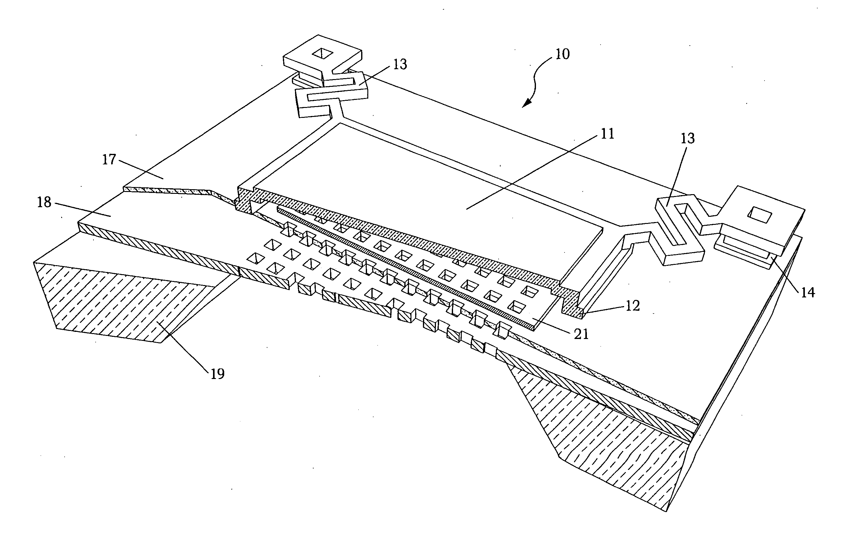
[0045] One embodiment of the microphone structure 10 according to the present invention is shown in the perspective view of FIG. 7 and the cross-sectional view of FIG. 8. An electrically conductive diaphragm 11 is attached to a supporting substrate 19 by a number of flexible suspension structures 13. Conductive diaphragm 11 can be a single layer conductive material, or be comprised of several layers of which at least one is conductive. Suspension structures 13 are attached to supporting substrate 19 using a conducting anchor material 14. Diaphragm 11 contains an annular indentation 12 at the perimeter, which in the initial position forms a narrow air gap 16 with supporting substrate 19. Supporting substrate 19 is coated with an electrically insulating layer 17, which isolates the conductive diaphragm 11 and a fixed counter electrode. A fixed counter electrode 21 is made of conductive layer 14, insulator 17, and a bulk layer 18. The purpose of bulk layer 18 is to provide sufficient m...


PUM

PropertyMeasurementUnit
DC bias voltageaaaaaaaaaa
corner frequencyaaaaaaaaaa

Abstract

An acoustic pressure type sensor fabricated on a supporting substrate is disclosed. The acoustic sensor is fabricated by depositing and etching a number of thin films on the supporting substrate and by machining the supporting substrate. The resulting structure contains a pressure sensitive, electrically conductive diaphragm positioned at a distance from an electrically conductive fixed electrode. In operation, the diaphragm deflects in response to an acoustic pressure and the corresponding change of electrical capacitance between the diaphragm and the fixed electrode is detected using an electrical circuit. Two or more such acoustic sensors are combined on the same supporting substrate with an interaural flexible mechanical connection, to form a directional sensor with a small surface area.

Description

FIELD OF THE INVENTION [0001] The present invention relates to the field of acoustic transducers, and more specifically to a microfabricated airborne acoustic microphone using micro electro-mechanical systems (MEMS). BACKGROUND OF THE INVENTION [0002] The emergence of micro fabrication technology has led to a number of developments in the field of airborne acoustic sensors (microphones). Traditionally, the most common technology for microphones has been the use of an electret to detect a deflection of a diaphragm caused by a differential acoustic pressure. Electrets are insulators (such as Teflon or Mylar) on which an electrical charge is trapped. An electret is used in a microphone to produce the necessary electrical field in the air gap between the electrically conductive movable diaphragm and fixed electrode to detect the deflection of the diaphragm. Alternatively, a DC potential between the diaphragm and fixed electrode may be applied from an external source to create the electr...

Claims


Application Information

Patent Timeline
Patent Type & Authority Applications(United States)
IPC IPC(8): H04R25/00H04R19/00
CPCB81B3/0072B81B2201/0257B81B2203/0127Y10T29/4902Y10T29/49005Y10T29/4908H04R19/005H01L2224/16H01L2924/15151H01L2924/16152
Inventor PEDERSEN, MICHAEL
Owner FOR NAT RES INITIATIVES
Why Eureka
Try Eureka