Effusion cooled dual wall gas turbine combustors

a gas turbine and combustible technology, applied in the direction of machines/engines, mechanical equipment, lighting and heating apparatus, etc., can solve the problems of affecting the service life of combustor, complication of combustor construction, and suffering certain drawbacks

Active Publication Date: 2011-02-03
HONEYWELL INT INC
View PDF19 Cites 55 Cited by
  • Summary
  • Abstract
  • Description
  • Claims
  • Application Information

AI Technical Summary

Problems solved by technology

The combustors in gas turbine engines typically operate at relatively high temperatures, including temperatures over 3500° F. Such high temperatures can adversely impact the service life of a combustor.

Method used


Image

  • Effusion cooled dual wall gas turbine combustors
  • Effusion cooled dual wall gas turbine combustors
  • Effusion cooled dual wall gas turbine combustors

Examples


Embodiment Construction

[0016]The following detailed description is merely exemplary in nature and is not intended to limit the invention or the application and uses of the invention. Furthermore, there is no intention to be bound by any theory presented in the preceding background or the following detailed description.

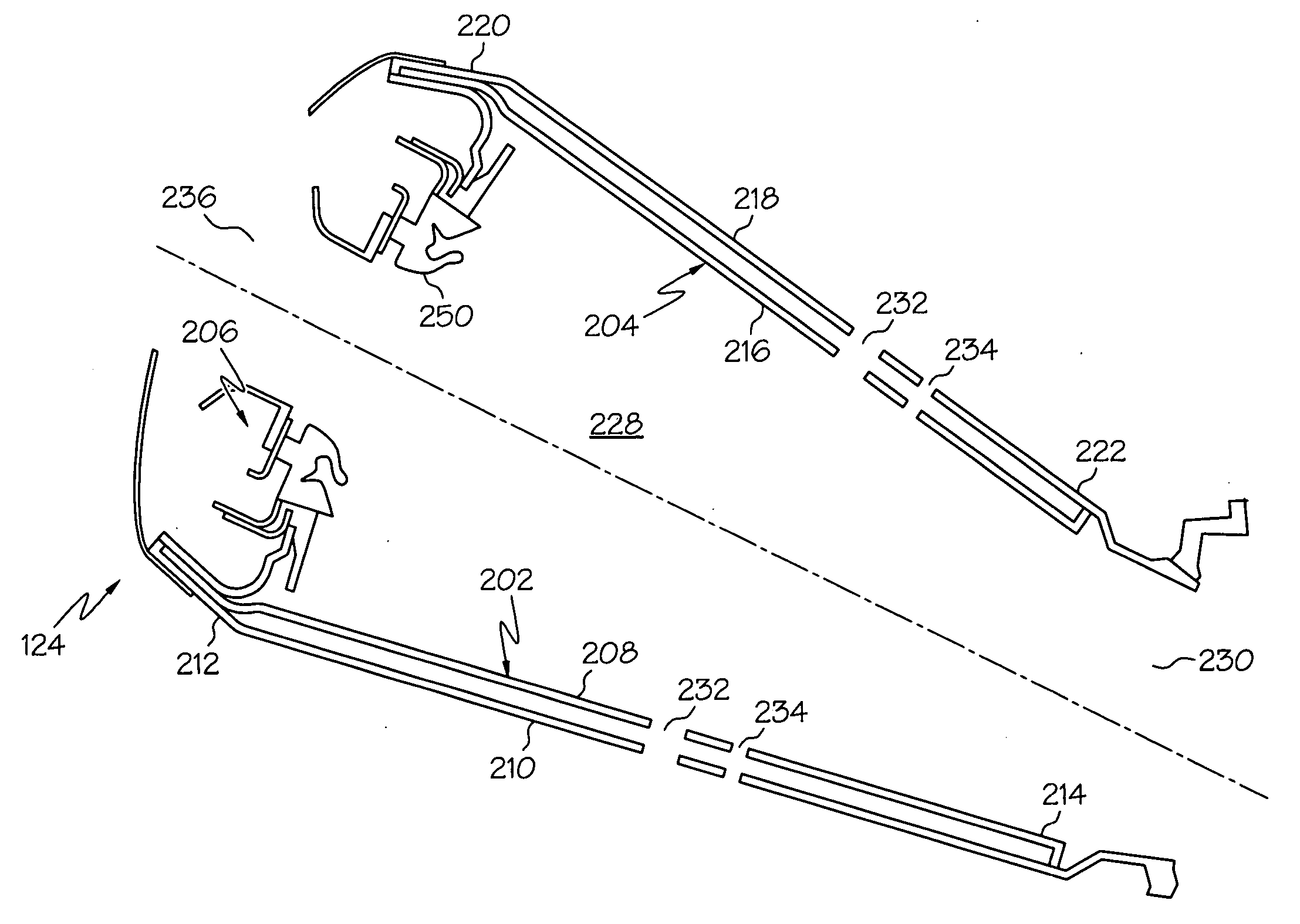
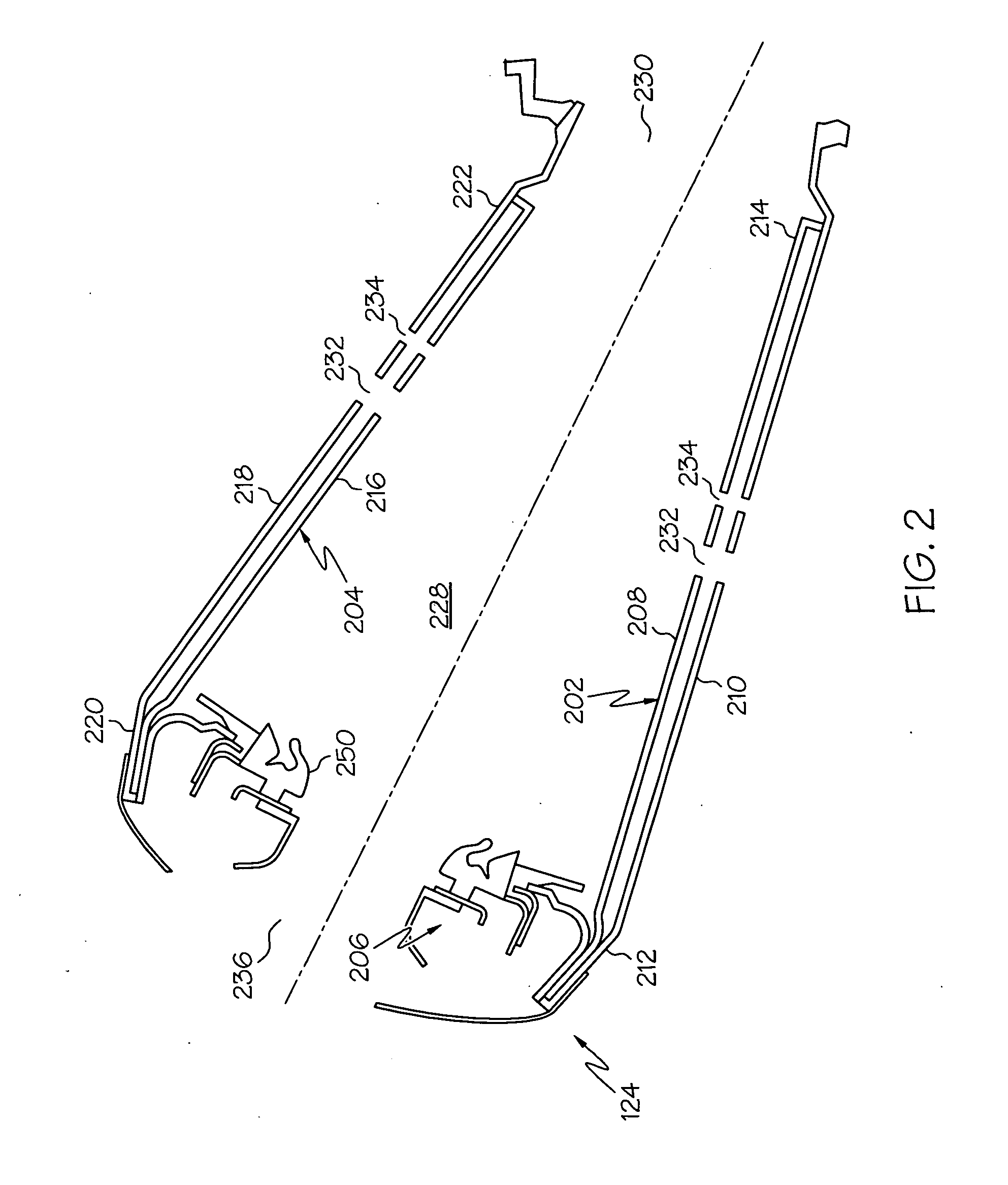
[0017]Broadly, exemplary embodiments disclosed herein provide dual wall combustors with liners having hot and cold walls. The hot wall may include an upstream row of effusion cooling holes disposed in a tangential direction and a downstream row of effusion cooling holes disposed in an axial direction. Downstream of dilution openings, the hot wall may have another row with effusion cooling holes disposed in the tangential direction. The combustor may further have impingement cooling holes in the cold wall of the dual wall liner.

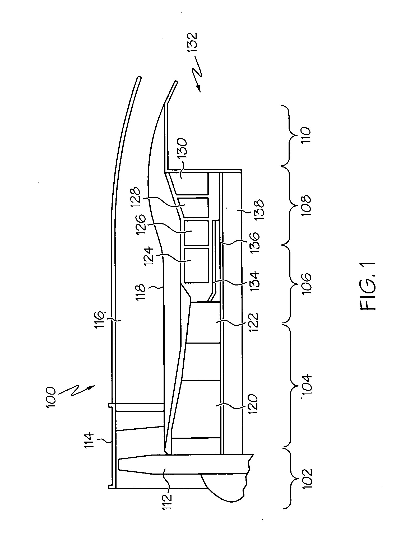
[0018]An exemplary embodiment of a multi-spool turbofan gas turbine jet engine 100 is depicted in FIG. 1, and includes an intake section 102, a compressor section 104,...


PUM


Abstract

A gas turbine engine combustor is provided. An inner liner has an upstream end and a downstream end and extends in an axial direction between the upstream and downstream ends. A dual wall outer liner has a hot wall, a cold wall at least partially surrounding the hot wall, an upstream end, and a downstream end. The outer liner extends in the axial direction between the upstream and downstream ends. A dome assembly is coupled between the upstream ends of the inner and outer liners to define a combustion chamber between the inner liner and the hot wall of the outer liner. Effusion cooling holes are disposed in the hot wall, including a first row disposed at a tangential angle of between about 70° and about 90° and a second row disposed at a tangential angle of between about 0° and about 20°.

Description

TECHNICAL FIELD[0001]The present invention relates to gas turbine engines, and more particularly, to dual wall, gas turbine engine combustors.BACKGROUND[0002]A gas turbine engine may be used to power various types of vehicles and systems. A particular type of gas turbine engine that may be used to power aircraft is a turbofan gas turbine engine. A turbofan gas turbine engine conventionally includes, for example, five major sections: a fan section, a compressor section, a combustor section, a turbine section, and an exhaust section. The fan section is typically positioned at the inlet section of the engine and includes a fan that induces air from the surrounding environment into the engine and accelerates a portion of this air toward the compressor section. The remaining portion of air induced into the fan section is accelerated into and through a bypass plenum and out the exhaust section.[0003]The compressor section raises the pressure of the air received from the fan section. The c...

Claims


Application Information

Patent Timeline
IPC IPC(8): F02C7/12
CPCF23R3/06Y02T50/675F23R2900/03044F23R2900/03041F23R3/005Y02T50/60
Inventor BRONSON, THOMAS J.ZUPANC, FRANK JOSEPHYANKOWICH, PAULRUDRAPATNA, NAGARAJA
Owner HONEYWELL INT INC
Why Eureka
Try Eureka