

Magnetic block for a water knife
- Summary
- Abstract
- Description
- Claims
- Application Information
AI Technical Summary
Benefits of technology
Problems solved by technology
Method used
Image

Examples
Embodiment Construction
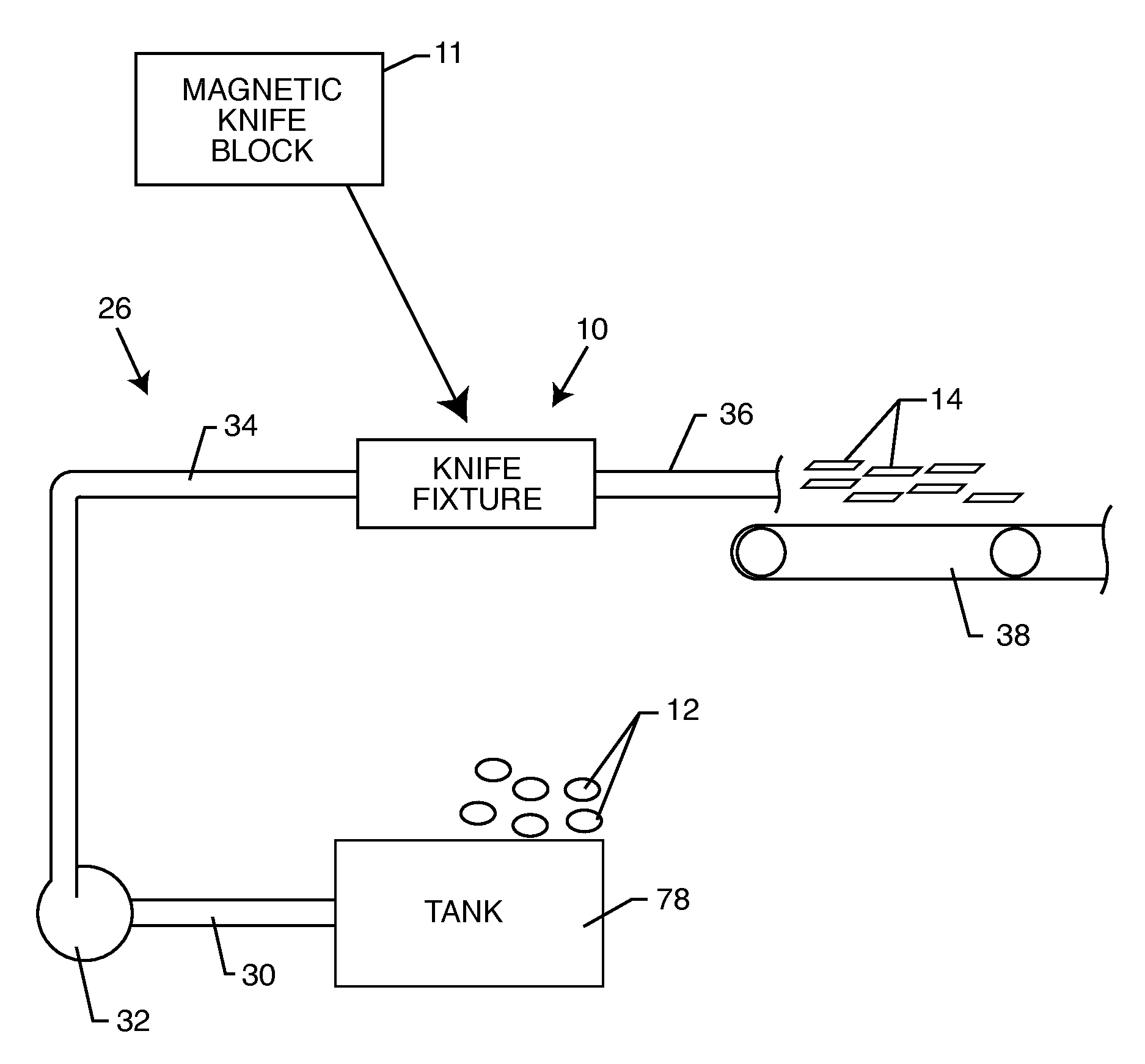
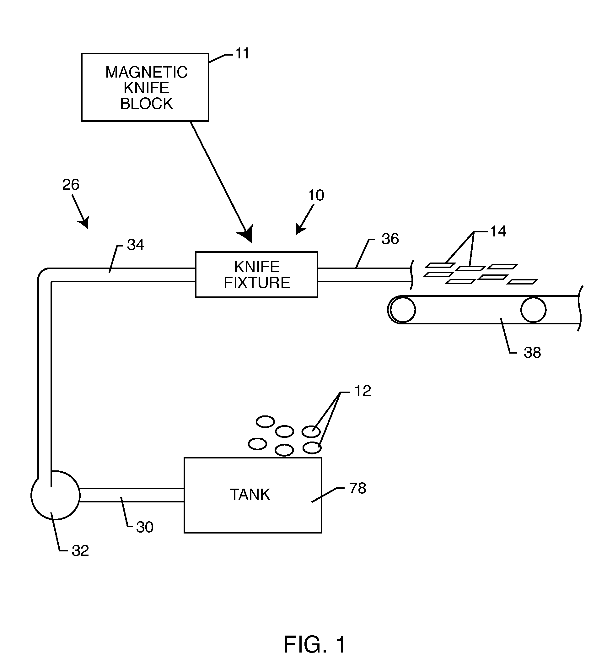
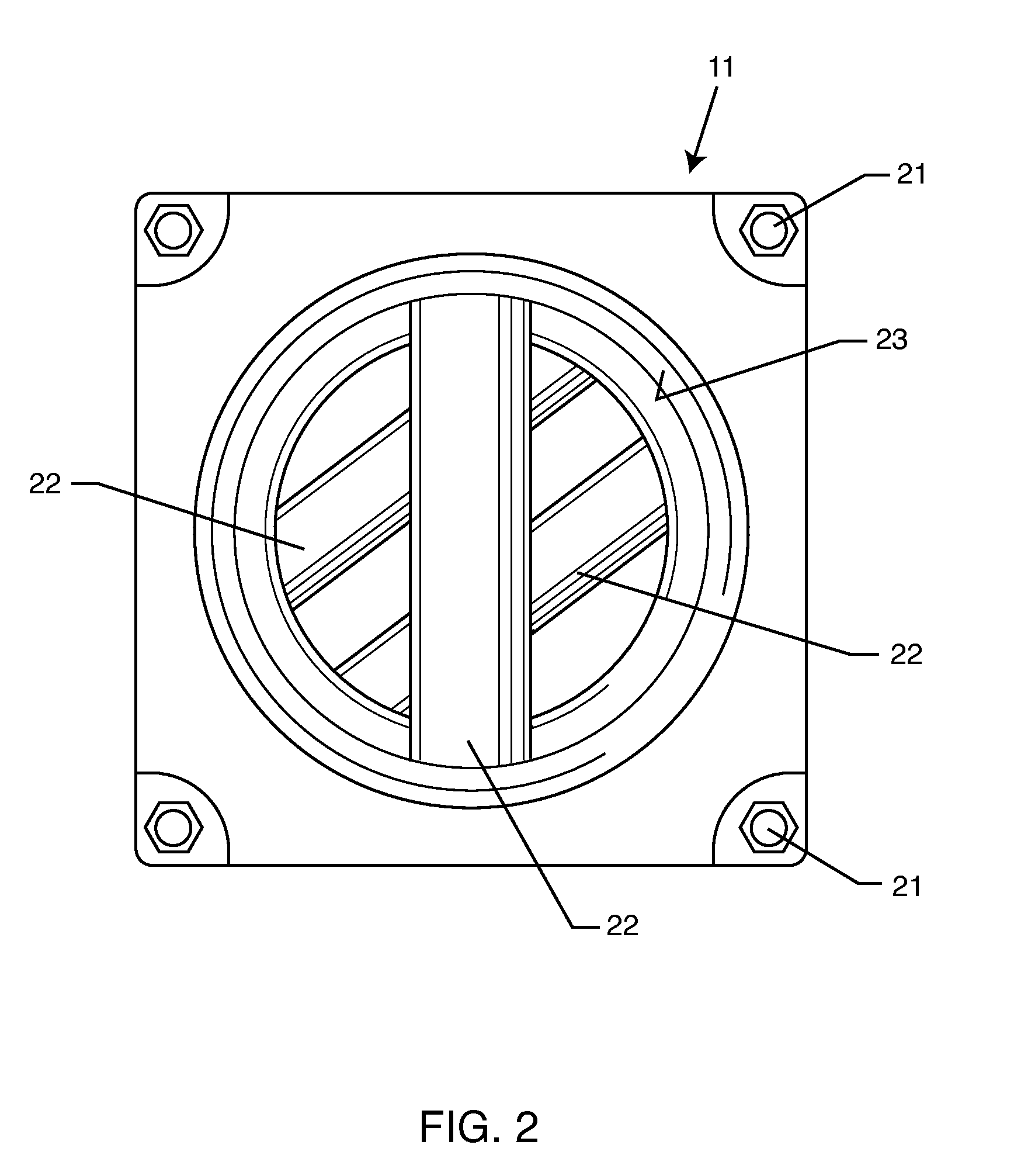
[0014]As shown in the exemplary drawings, an hydraulic cutting system comprises a conventional so-called water knife fixture referred to generally in FIG. 1 by the reference numeral 10 to cutting vegetable products such as whole potatoes 12 into elongated strips 14, such as French fry strips for subsequent processing. The present invention comprises a magnetic knife block 11 for temporary installation into the cutting system, in lieu of the water knife fixture 10, for collecting unwanted metal fragments and / or metal debris arising from construction and / or maintenance activities. After use the of the magnetic knife block 11, the block 11 is replaced quickly and easily by the conventional water knife fixture 10 for normal production cutting of the elongated strips 14.
[0015]FIG. 1 shows the hydraulic cutting system to comprise a tank 78 or the like for receiving a supply of vegetable products, such as the illustrative raw whole potatoes 12. These potatoes 12 are delivered via an inlet ...
PUM
| Property | Measurement | Unit |
|---|---|---|
| Size | aaaaa | aaaaa |
| Flexibility | aaaaa | aaaaa |
| Magnetism | aaaaa | aaaaa |
Abstract
Description
Claims
Application Information