
Liquid container

Inactive Publication Date: 2011-02-03
ROHTO PHARM CO LTD
View PDF18 Cites 24 Cited by
  • Summary
  • Abstract
  • Description
  • Claims
  • Application Information

AI Technical Summary

Benefits of technology

The present invention has been made in view of the above circumstances, and an object thereof is to allow a cap to be adequately guided and attached to a container body, while preventing a disadvantage such as deformation of a nozzle.
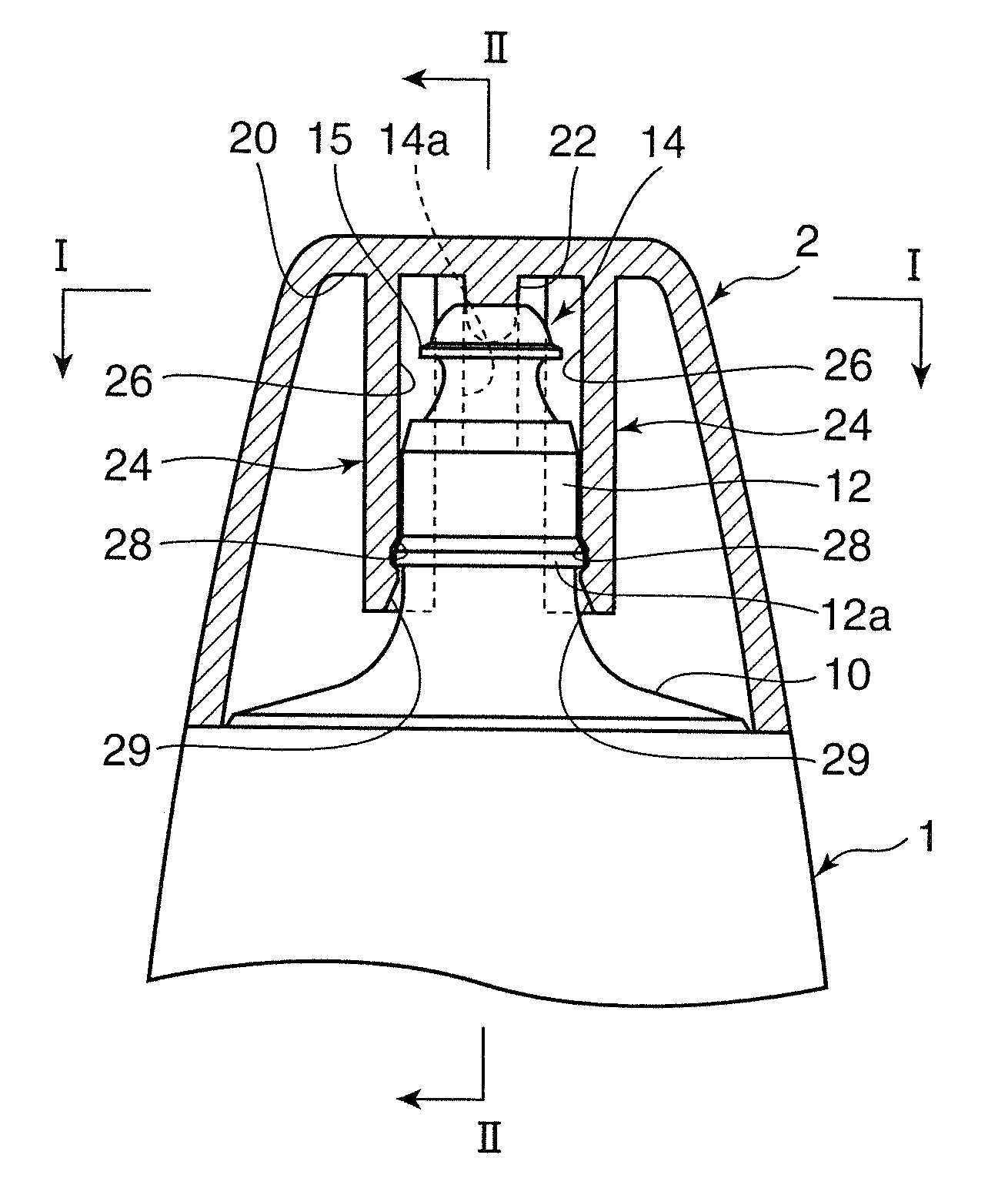
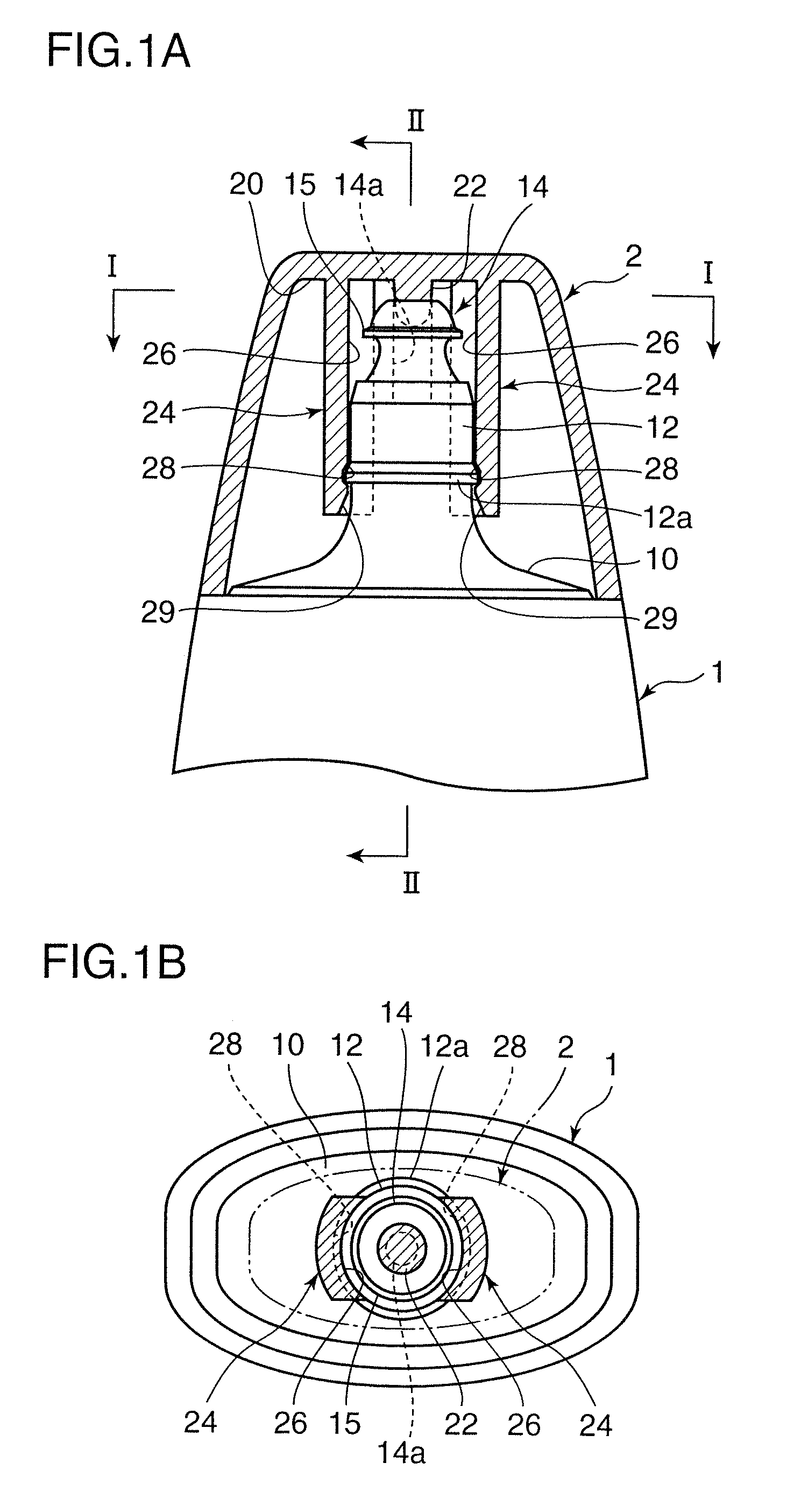
In this liquid container, when the cap is attached along the axial direction of the tubular neck portion of the container body, the nozzle portion and the tubular neck portion are inserted between the pair of lockable pieces provided on the inner top region of the cap, and the respective guide surfaces of the lockable pieces come into contact with the outer peripheral surface of the tubular neck portion to guide the cap along the axial direction of the tubular neck portion. The cap is guided along the guide surfaces of the lockable pieces in the above manner, so that the nozzle hole is aligned with the sealing portion. Then, when the cap is pushed along the axial direction of the tubular neck portion to a given dead end position, the locking protrusion of the tubular neck portion is inserted into the locking concave portions formed in the opposing surfaces of the lockable pieces, and thereby the cap is locked with respect to the container body. Thus, this liquid container is free of guiding the nozzle portion while bringing it into contact along a guide portion provided on the cap as in the conventional container, so that it becomes possible to prevent deformation or the like in the nozzle due to the contact. In addition, the guide surfaces for the tubular neck portion are integrally provided on the lockable pieces for locking the cap to the container body, so that the aforementioned effects can be obtained with a rational structure.
Specifically, the ring-shaped protrusion is formed on the outer periphery of the nozzle portion to prevent dripping from the nozzle portion and allow a droplet to be adequately formed irrespective of a posture (instillation angle) of the container body to improve instillation performance. The above structure is free of guiding the nozzle portion while bringing it into contact along a guide portion provided on the cap, during the cap attaching operation, so that it becomes possible to prevent deformation or the like in the ring-shaped protrusion and thus adequately maintain the aforementioned functions on a long-term basis.

Problems solved by technology

However, in the container described in JP 10-329855A, during the cap attaching operation, a nozzle portion is guided while being brought into contact along a guide portion provided on the cap, so that repetition of the cap attaching / detaching operations would be likely to cause deformation or the like in the nozzle, which poses a problem for droplet formation.
Moreover, only the distal end of the ring-shaped protrusion is brought into contact along the guide portion of the cap in the above manner, so that there is another problem of difficulty in stably guiding the nozzle along the guide portion during the cap attaching operation.

Method used


Image

  • Liquid container
  • Liquid container
  • Liquid container

Examples


Embodiment Construction

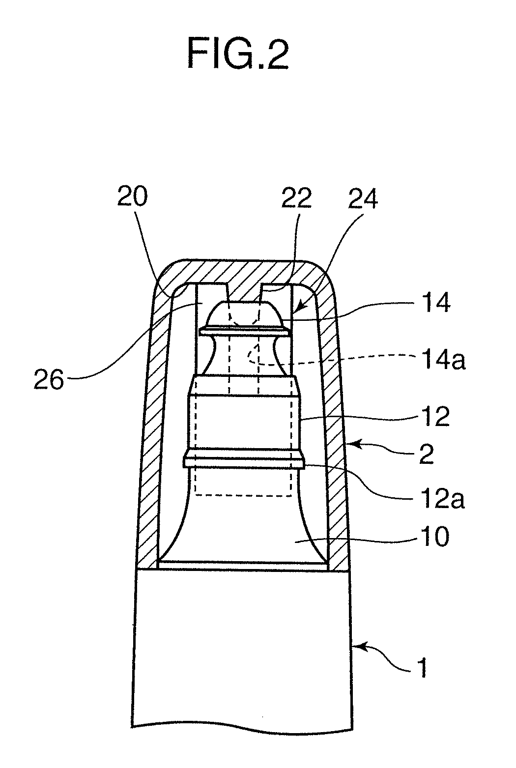
FIGS. 1 and 2 illustrate a substantial part of a liquid container according to the present invention.

The liquid container (hereinafter abbreviated as “container”) illustrated in FIGS. 1 and 2 is a so-called twist cap-type container. In this embodiment, this container is an eye drop container which comprises a container body 1 having a nozzle portion 14, and a cap 2 detachably attachable to the container body 1 to cover the nozzle portion 14, wherein it is designed, during instillation, to allow a medical solution contained in the container body 1 to be instilled from a tip end of the nozzle portion through an operation of gently pressing the container body 1 while orienting the tip end of the nozzle portion downwardly under a condition that the cap 2 is detached.

As shown in FIG. 1(b), the container body 1 is formed in a flat shape in a forward-rearward direction (upward-downward direction in FIG. 1(b)). The container body 1 is configured such that a circular tubular neck portion 12 ...


PUM


Abstract

A liquid container has a body (1) and a cap (2). A circular tubular neck (12) of the body (1) has an outer diameter greater than a maximum diameter of a nozzle (14), and a locking protrusion (124) for the cap (2) is provided on an outer peripheral surface of the circular tubular neck. The cap (2) has two lockable arms (24). The lockable arms (24) are locked onto the locking protrusion (12a) while attaching the cap (2) to the body (1). Opposing surfaces (26) of the lockable arms (24) define guide surfaces that contact the outer peripheral surface of the circular tubular neck (12) during the cap attaching operation to guide the cap (2) along the circular tubular neck (12) so as to allow a plug protrusion (22) of the cap (2) and a nozzle hole (14a) to oppose each other.

Description

BACKGROUND OF THE INVENTION1. Field of the InventionThe present invention relates to a liquid container useful as a container for an eye drop (ophthalmic solution), a nose drop (nasal solution), a contact-lens cleaning solution or the like.2. Description of the Related ArtHeretofore, as a container for an eye drop or the like, there has been commonly known a type which comprises a container body having a nozzle, and a cap detachably attachable to the container body, wherein it is designed to allow a medical solution to be instilled (dropped) from a tip end of the nozzle through an operation of gently pressing the container body while orienting the tip end of the nozzle downwardly under a condition that the cap is detached.Particularly, a so-called twist cap-type liquid container having a lockable arm provided on an inner peripheral surface of a cap is widely used as the container for an eye drop or the like, wherein it is designed such that the cap is attached to a container body by...

Claims


Application Information

Patent Timeline
IPC IPC(8): B65D45/00B65D25/40
CPCB65D47/18B65D41/485
Inventor KOKUBO, SHIGEHIKO
Owner ROHTO PHARM CO LTD
Learn More