Bottom Blade Type Vehicle

a technology of bottom blades and blades, which is applied in the direction of micro-sized aircraft, transportation and packaging, toys, etc., can solve the problems of reduced power efficiency, complicated structure and adjusting devices, etc., and achieve the effects of simple structure and adjustment, reduced power efficiency, and simplified structure and adjustment devices

Inactive Publication Date: 2011-02-03
HANLEY CHINA +1
View PDF2 Cites 7 Cited by
  • Summary
  • Abstract
  • Description
  • Claims
  • Application Information

AI Technical Summary

Benefits of technology

[0011]As described above, the conventional bottom blade type vehicle uses the variable screw-pitch rotor that needs to be repeatedly adjusted on the helix angles or the long adjusting blades that are mounted in the transverse shaft for realizing the balance and stability of the vehicle during its forward or backward flight. Besides, for maintaining the vehicle balanced and stable, the installed variable screw-pitch rotor needs to be adjusted. The adjusting blades are installed and adjusted to offset the left or right rotation of the vehicle. However, the structure and the adjusting device are complicated and have the problem of reduced power efficiency. On contrary, in the present invention, the weight of the vehicle is evenly distrib...

Problems solved by technology

However, the structure and the adjusting device are c...

Method used


Image

  • Bottom Blade Type Vehicle
  • Bottom Blade Type Vehicle
  • Bottom Blade Type Vehicle

Examples


Embodiment Construction

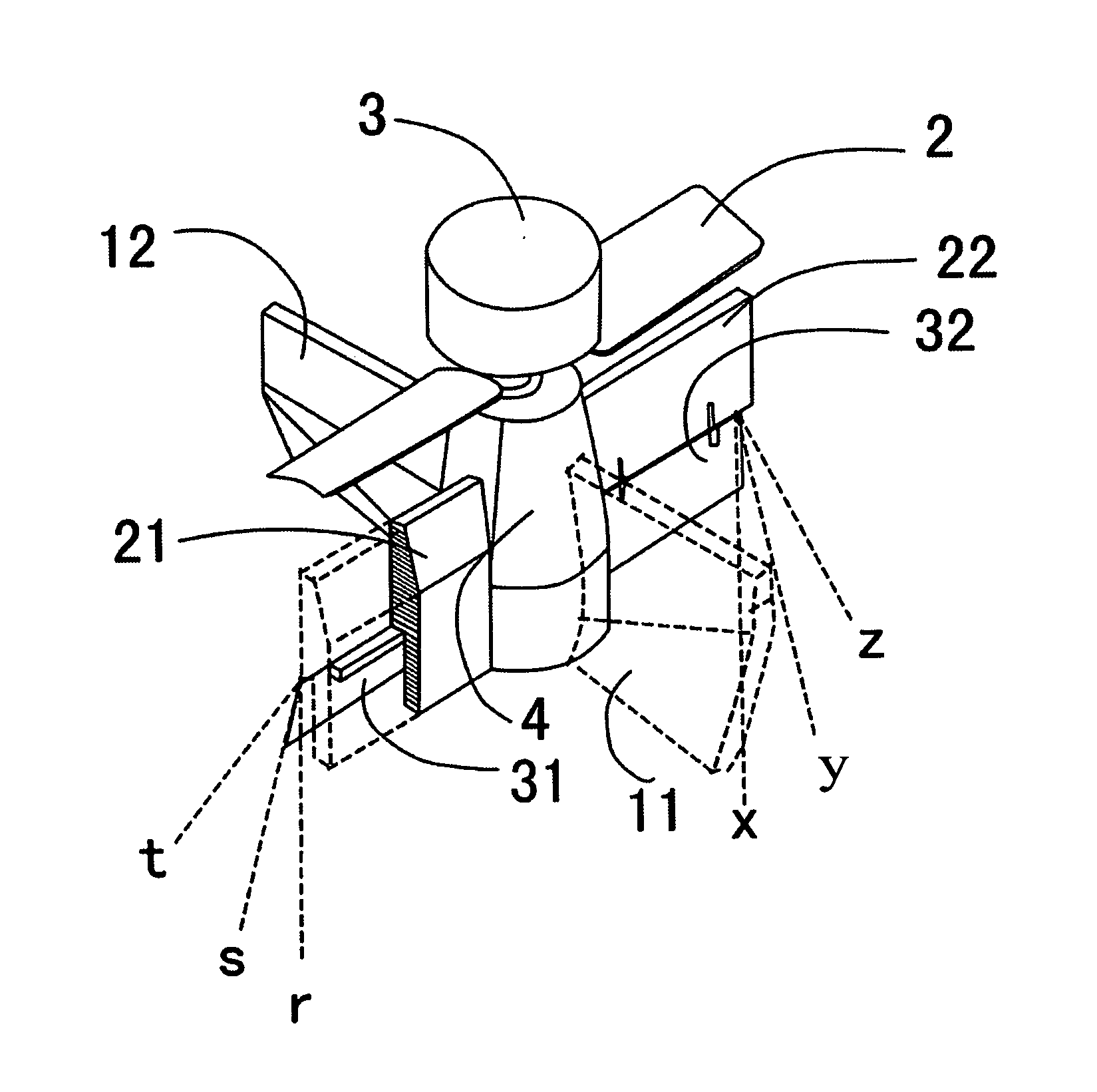
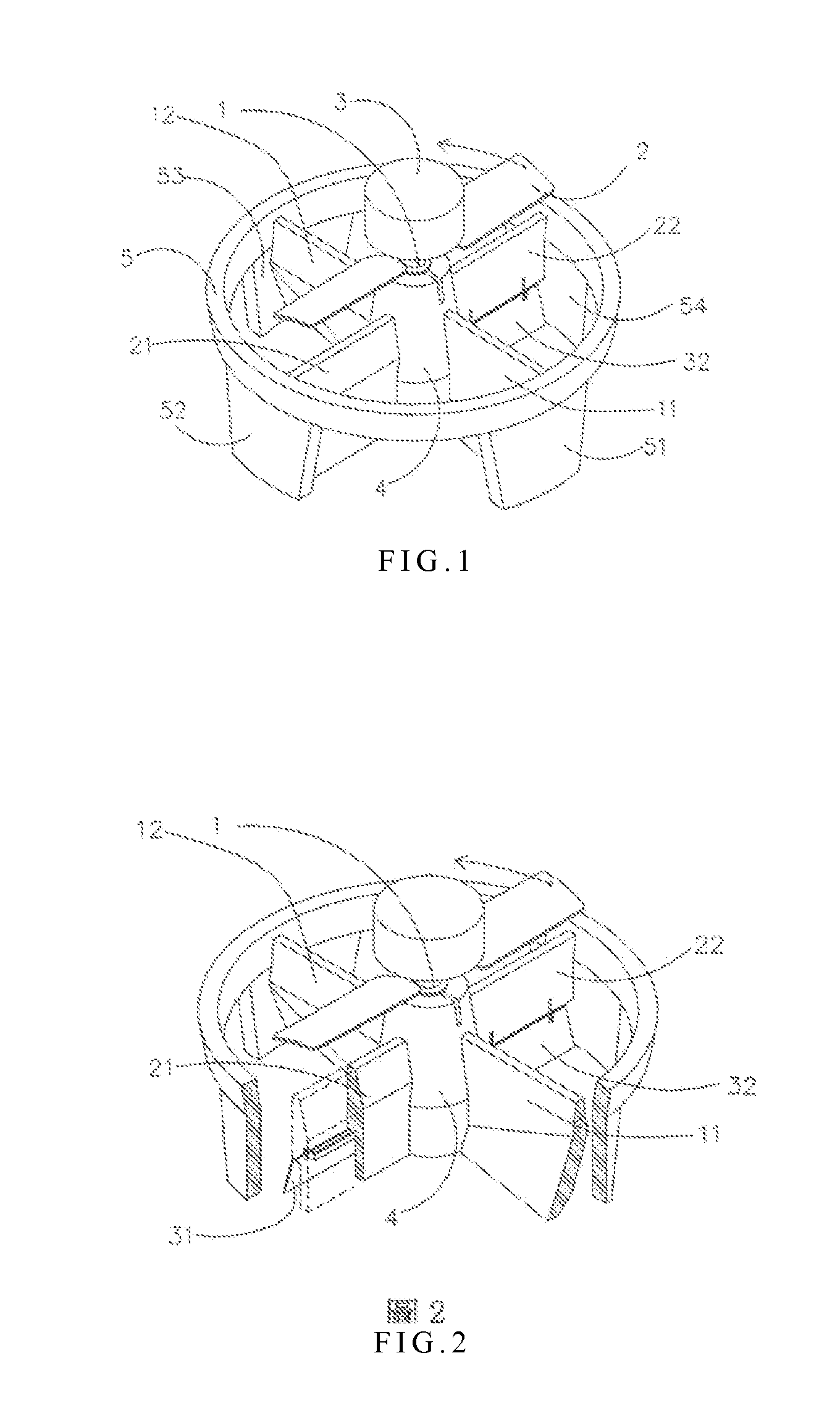
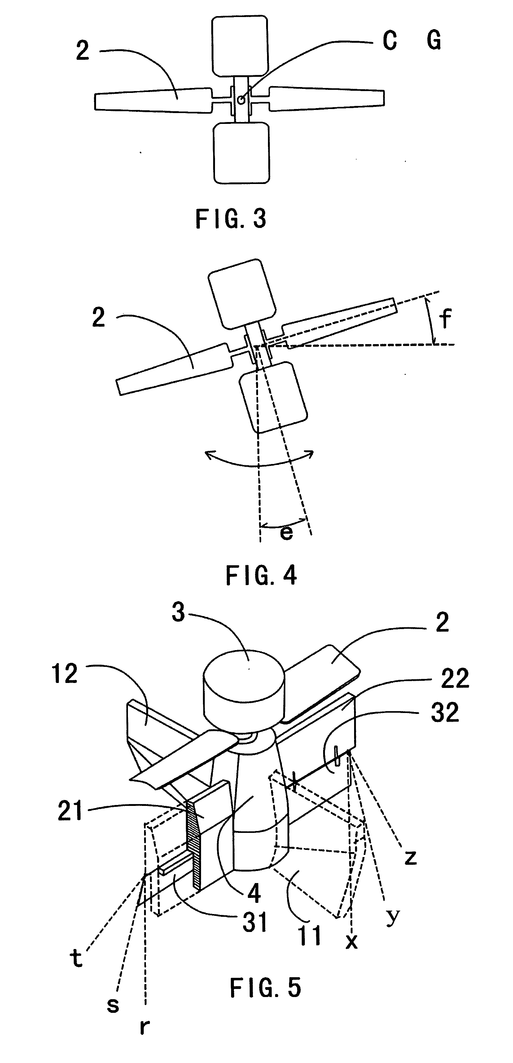
[0042]Please refer to FIGS. 1 and 2 for the entire structure of a bottom blade type vehicle of the present invention that achieves the aforementioned objective.

[0043]In the present invention, a fixed screw-pitch leaf 2 is horizontally mounted taking a center axis 1 as the center. A power part 3 is mounted above the leaf 2 while a controlling part 4 is mounted under the leaf. In addition, a first and a second fixing plates 11, 12 and a first and a second protecting plates 21, 22 are crossed each other in a cross-shape taking the controlling part as the center. The cross-shape assembly is vertically connected inward to the controlling part and connected outward vertically to a round frame 5 and bridge plates 51, 52, 53, and 54. A first and a second adjusting blades 31, 32 controlled by a controlling device of the controlling part 4 are mounted on the first and the second protecting plates 21, 22, respectively.

[0044]As shown in FIG. 1, the round frame 5 of the present invention is a ro...


PUM


Abstract

A bottom blade type vehicle includes a fixed screw-pitch leaf horizontally mounted taking a center axis as the center; a power part mounted above the leaf; a controlling part mounted under the leaf; a first and a second fixing plates and a first and a second protecting plates being crossed each other in a cross-shape taking the controlling part as the center, one end of the first and the second fixing plates and the first and the second protecting plates connected to the controlling part and the other end of them connected to a round frame; a bridge plate vertically fixedly mounted under the round frame; and a first and a second adjusting controlled by a controlling device of the controlling part, wherein the first and the second adjusting blades are mounted on the first and the second protecting plates respectively.

Description

BACKGROUND OF THE INVENTION[0001]1. Technical Field[0002]The present invention relates to pilotless rotary-wing aircrafts, and more particularly, to a bottom blade type vehicle.[0003]2. Description of Related Art[0004]Conventionally, a bottom blade type vehicle comprises a rotor and leaves powered to rotate taking a center axis as the center, and also includes a power part, a controlling part, fixing plates, and adjusting blades. Among the known approaches to controlling the flight direction and achieving the flight stability of the existing bottom blade type vehicle, it is a popular one to implement a variable screw-pitch rotor that has plural leaves whose helix angles are to be repeatedly adjusted for controlling the flight direction of the vehicle. In another common approach, a transverse shaft are provided at the bottom of the vehicle for holding plural adjusting blades so that the flight direction of the vehicle can be controlled by adjusting the adjusting blades.[0005]However,...

Claims


Application Information

Patent Timeline
IPC IPC(8): B64C27/00
CPCA63H27/12B64C27/20B64C2201/088B64C2201/027B64C2201/042B64C39/028B64U30/21B64U10/13B64U50/19B64U70/80
Inventor CHOI, KEY DONG
Owner HANLEY CHINA
Why Eureka
Try Eureka