Calibration method for video and radiation imagers

a radiation imager and video-based technology, applied in the field of visible light camera image processing, can solve the problems of cross-calibration between the two types of imagers, and achieve the effect of minimizing the fitting error in the least square fitting

Inactive Publication Date: 2011-02-03
UT BATTELLE LLC
View PDF13 Cites 27 Cited by
  • Summary
  • Abstract
  • Description
  • Claims
  • Application Information

AI Technical Summary

Problems solved by technology

Because of the different geometry employed for the two types of imagers, cross-calibration between the two types of imagers poses a difficulty.

Method used


Image

  • Calibration method for video and radiation imagers
  • Calibration method for video and radiation imagers
  • Calibration method for video and radiation imagers

Examples


Embodiment Construction

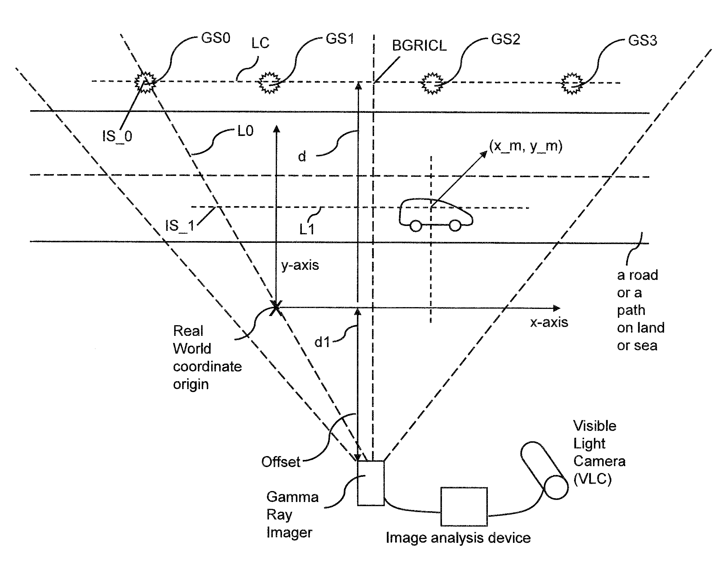
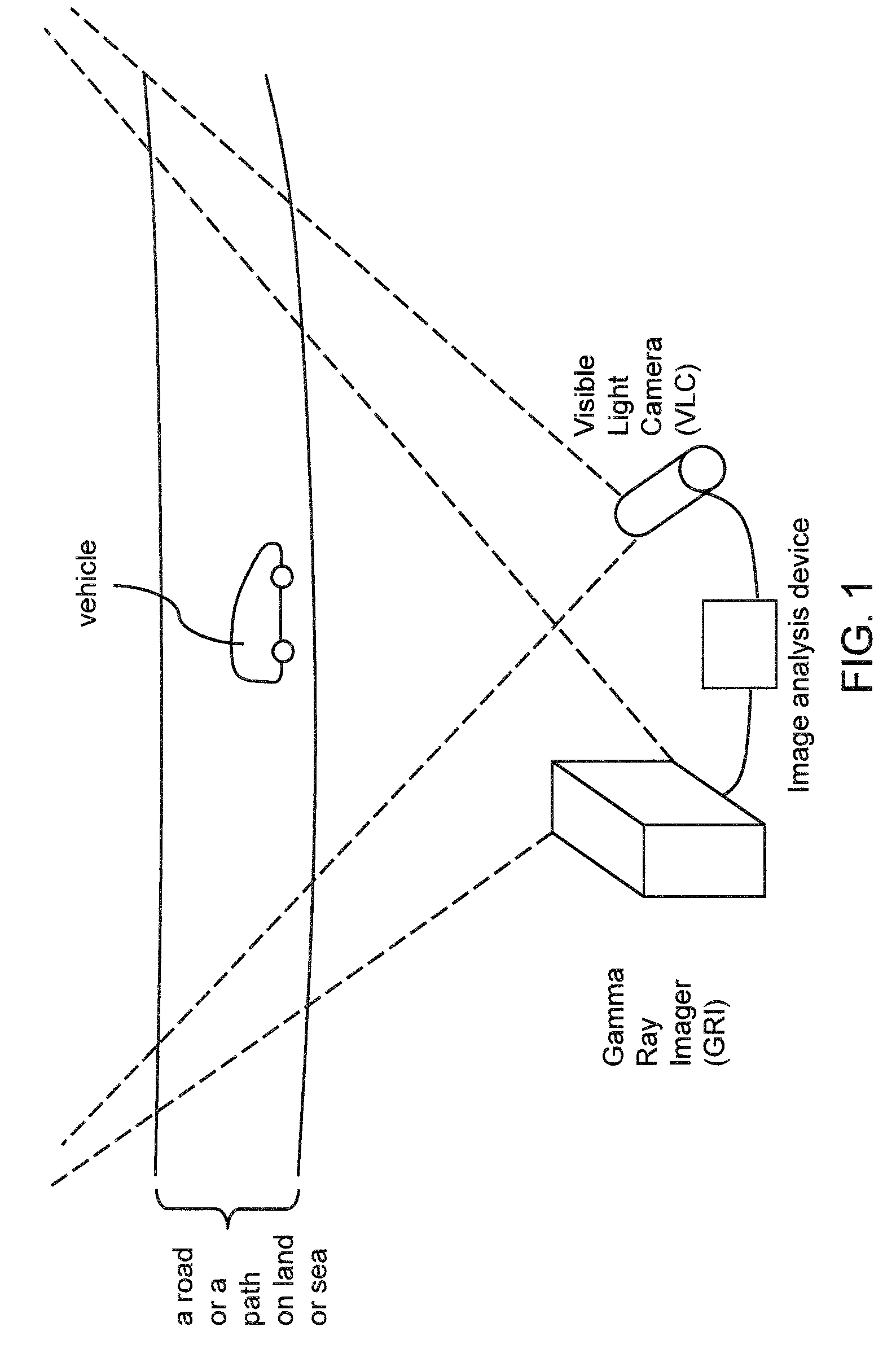
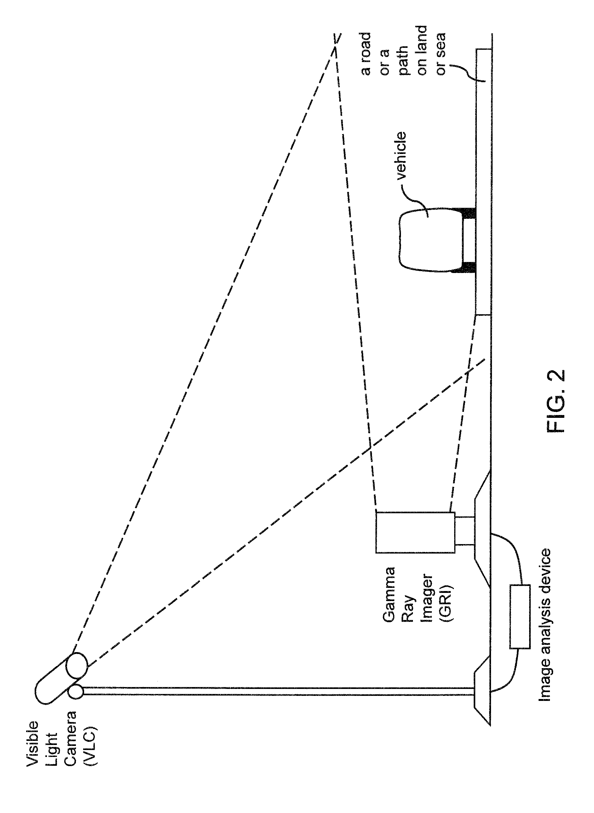
[0057]As stated above, the present invention relates to apparatus and methods for correlating high energy radiation imager pixels of a high energy radiation imager to a real-world coordinate of a moving vehicle. The present invention is now described in detail with accompanying figures. It is noted that like and corresponding elements mentioned herein and illustrated in the drawings are referred to by like reference numerals.

[0058]As used herein, “visible light camera images” refer to any type of data set in digital format that may be manipulated by a computing device.

[0059]As used herein, a “time series” refers to a group of at least two elements that are generated at different points in time.

[0060]As used herein, a “vehicle” refers to any transportation equipment that moves on a surface. A vehicle may be, but is not limited to, a car or a truck moving on a road or any other solid surface, a ship moving on water, or any other manned or unmanned object that moves on a solid surface ...


PUM


Abstract

The relationship between the high energy radiation imager pixel (HERIP) coordinate and real-world x-coordinate is determined by a least square fit between the HERIP x-coordinate and the measured real-world x-coordinates of calibration markers that emit high energy radiation imager and reflect visible light. Upon calibration, a high energy radiation imager pixel position may be determined based on a real-world coordinate of a moving vehicle. Further, a scale parameter for said high energy radiation imager may be determined based on the real-world coordinate. The scale parameter depends on the y-coordinate of the moving vehicle as provided by a visible light camera. The high energy radiation imager may be employed to detect radiation from moving vehicles in multiple lanes, which correspondingly have different distances to the high energy radiation imager.

Description

STATEMENT REGARDING FEDERALLY SPONSORED RESEARCH OR DEVELOPMENT [0001]This invention was made with United States government support under Prime Contract No. DE-AC05-00OR22725 awarded by the U.S. Department of Energy. The United States government has certain rights in this invention.FIELD OF THE INVENTION [0002]The present invention relates to the field of visible light camera image processing, and particularly to apparatus and methods for correlating high energy radiation imager pixels of a high energy radiation imager to a real-world coordinate of a moving vehicle.BACKGROUND OF THE INVENTION [0003]Rapid-deployment portal monitors employing visible light imaging and gamma ray imaging has been proposed. For example, K. Ziock, “The Use of Gamma-Ray Imaging to Improve Portal Monitor Performance,” 2007 IEEE Nuclear Science Symposium Conference, pp. 1198-1208 (2007) discloses simultaneous monitoring of multiple lanes of traffic from the side of a roadway. A roadside tracker may employ au...

Claims


Application Information

Patent Timeline
Patent Type & Authority Applications(United States)
IPC IPC(8): G01D18/00H01L27/00
CPCG01V5/0075H01L27/14601
Inventor CUNNINGHAM, MARK F.FABRIS, LORENZOGEE, TIMOTHY F.GODDARD, JR., JAMES S.KARNOWSKI, THOMAS P.ZIOCK, KLAUS-PETER
Owner UT BATTELLE LLC
Why Eureka
Try Eureka