Safety bumper

a bumper and safety technology, applied in the field of safety bumpers, can solve the problems of injuring or killing the occupants

Inactive Publication Date: 2011-02-03
ANAND SANDEEP KUMAR
View PDF7 Cites 2 Cited by
  • Summary
  • Abstract
  • Description
  • Claims
  • Application Information

AI Technical Summary

Benefits of technology

[0004]The main purpose of the present invention is to provide a bumper to prevent a sudden stop by absorbing shock impact and diverting oncoming vehicles after the collision.

Problems solved by technology

When two vehicles collide with each other it is the sudden impact of the vehicles that causes injuries to the occupants or kills them.
However, the crumple zone only provides a small distance of linear deceleration and, furthermore, crumples from any frontal direction without any deflection.

Method used


Image

  • Safety bumper
  • Safety bumper
  • Safety bumper

Examples


Embodiment Construction

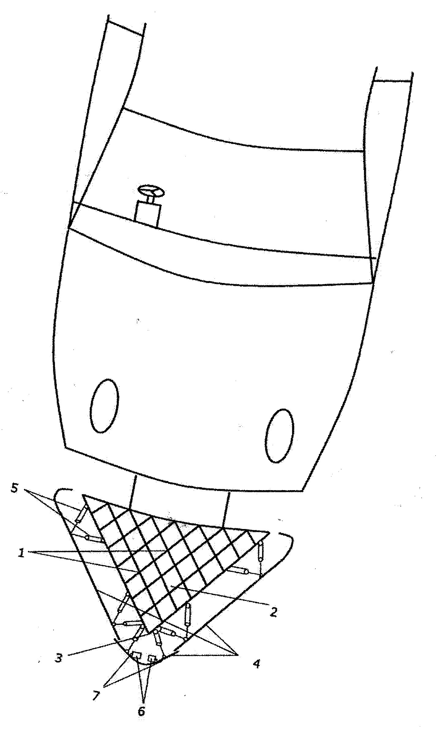
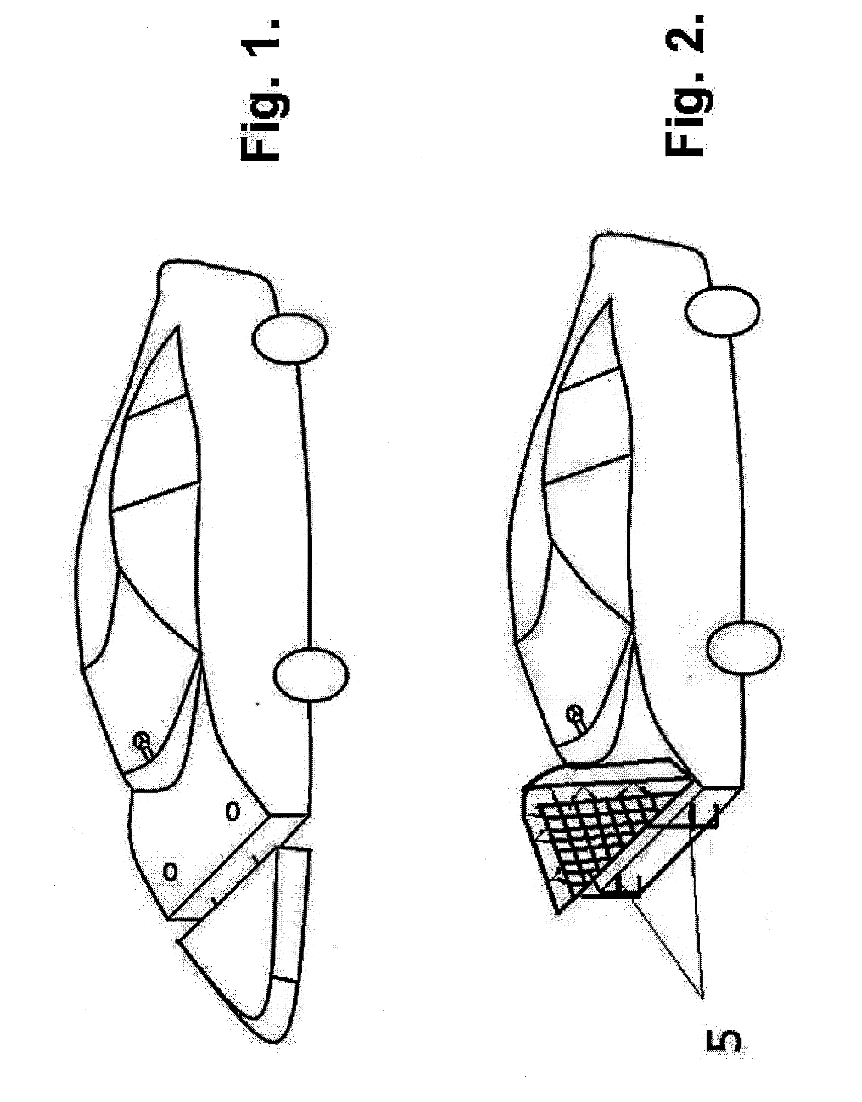
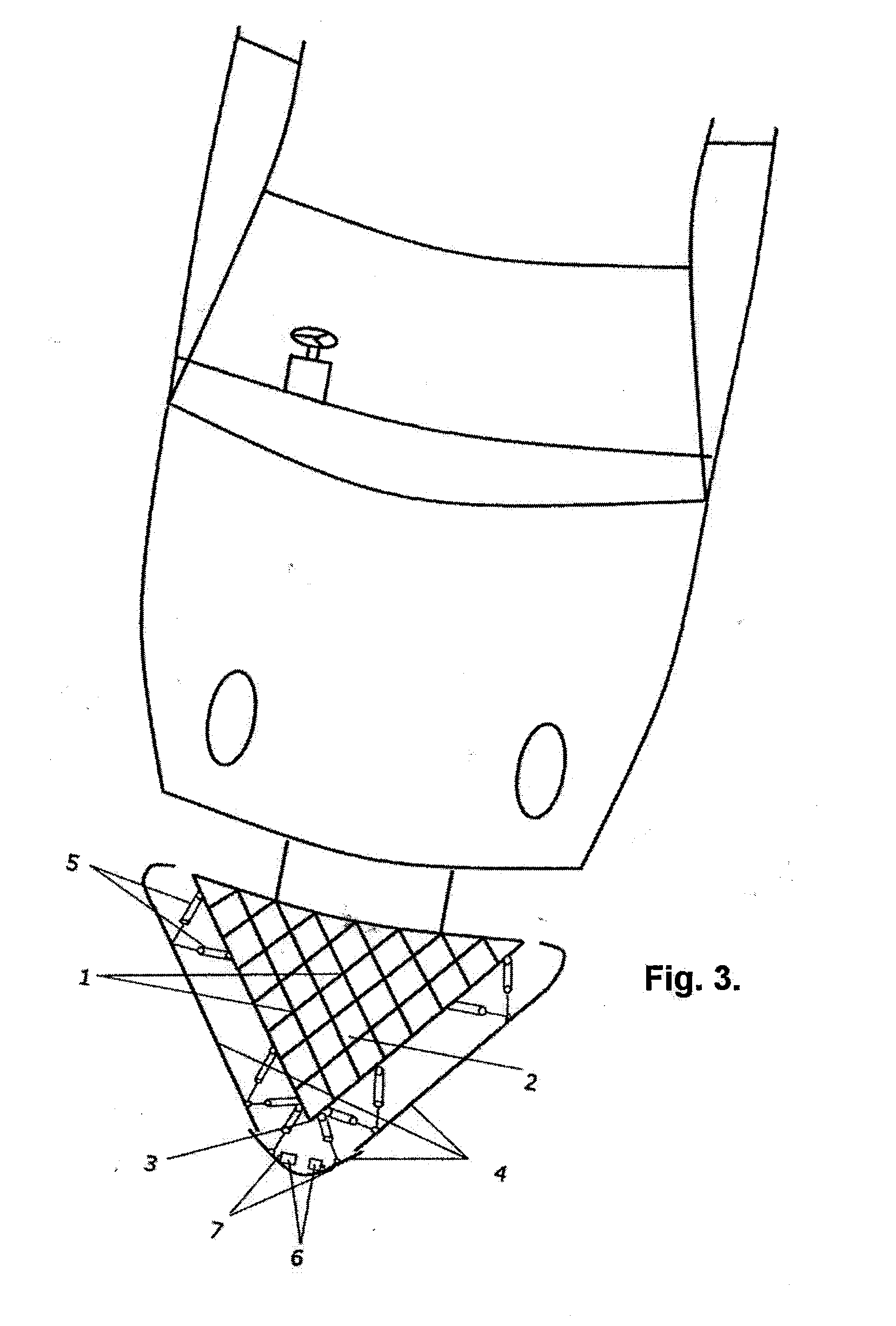
[0019]Referring to the drawings (particularly FIG. 3), the safety bumper of the invention is made of several elements, specifically panels 1, preferably of metal, vertically interlocked with each other to form a mesh or lattice pattern. The thickness of a panel can depend on the weight of the vehicle to which the bumper is fitted. The panels 1 effectively have diamond shaped gaps 2 between them and, on impact, are compressed to absorb most of the shock. During and after the collision, the V-shape 3 of the bumper pointing to the front diverts the colliding vehicles away from each other.

[0020]As best illustrated by FIG. 4C, each panel 1 consists of a generally elongate flat sheet (of metal) with notches cut out to mate with an adjacent panel. In practice the assembled lattice of FIG. 4B is mounted by its edge on top of a diamond-shaped array of metal bars (forming a supporting framework), e.g. by welding. It is generally positioned within a triangular enclosure as illustrated by FIG. ...


PUM


Abstract

A safety bumper for a vehicle constructed from a lattice of interlocking panels (1). The panels are formed in an overall substantive V, D or triangular shape such that when vehicle collide they are deflected from each other and, moreover, the bumper lattice crumples to give a progressive deceleration which reduces the risk of injury or death to passengers in the vehicle.

Description

TECHINCAL FIELD[0001]The invention relates to a safety bumper for cars and the like.BACKGROUND ART[0002]When two vehicles collide with each other it is the sudden impact of the vehicles that causes injuries to the occupants or kills them.[0003]This problem is addressed in modern cars by the introduction of a “crumple zone” where the bonnet of a car is constructed so it will be crushed on impact to provide a short distance of deceleration before the vehicle completely stops. In other words, energy is transformed by the deformation of the vehicle bonnet instead of being directly transmitted through the body of an occupant. However, the crumple zone only provides a small distance of linear deceleration and, furthermore, crumples from any frontal direction without any deflection.DISCLOSURE OF THE INVENTION[0004]The main purpose of the present invention is to provide a bumper to prevent a sudden stop by absorbing shock impact and diverting oncoming vehicles after the collision.[0005]In a...

Claims


Application Information

Patent Timeline
Patent Type & Authority Applications(United States)
IPC IPC(8): B60R19/02
CPCB60R19/00B60R2019/005B62D39/00B60T7/22B60R2019/1813
Inventor ANAND, SANDEEP KUMAR
Owner ANAND SANDEEP KUMAR
Why Eureka
Try Eureka