
Systems, methods and apparatus for vehicle battery charging

a technology for vehicle batteries and charging devices, applied in the field of vehicle batteries, can solve problems such as difficulty in recharging and specific connectors which may not be universal

Active Publication Date: 2011-02-03
DEKA PROD LLP
View PDF8 Cites 342 Cited by
  • Summary
  • Abstract
  • Description
  • Claims
  • Application Information

AI Technical Summary

Benefits of technology

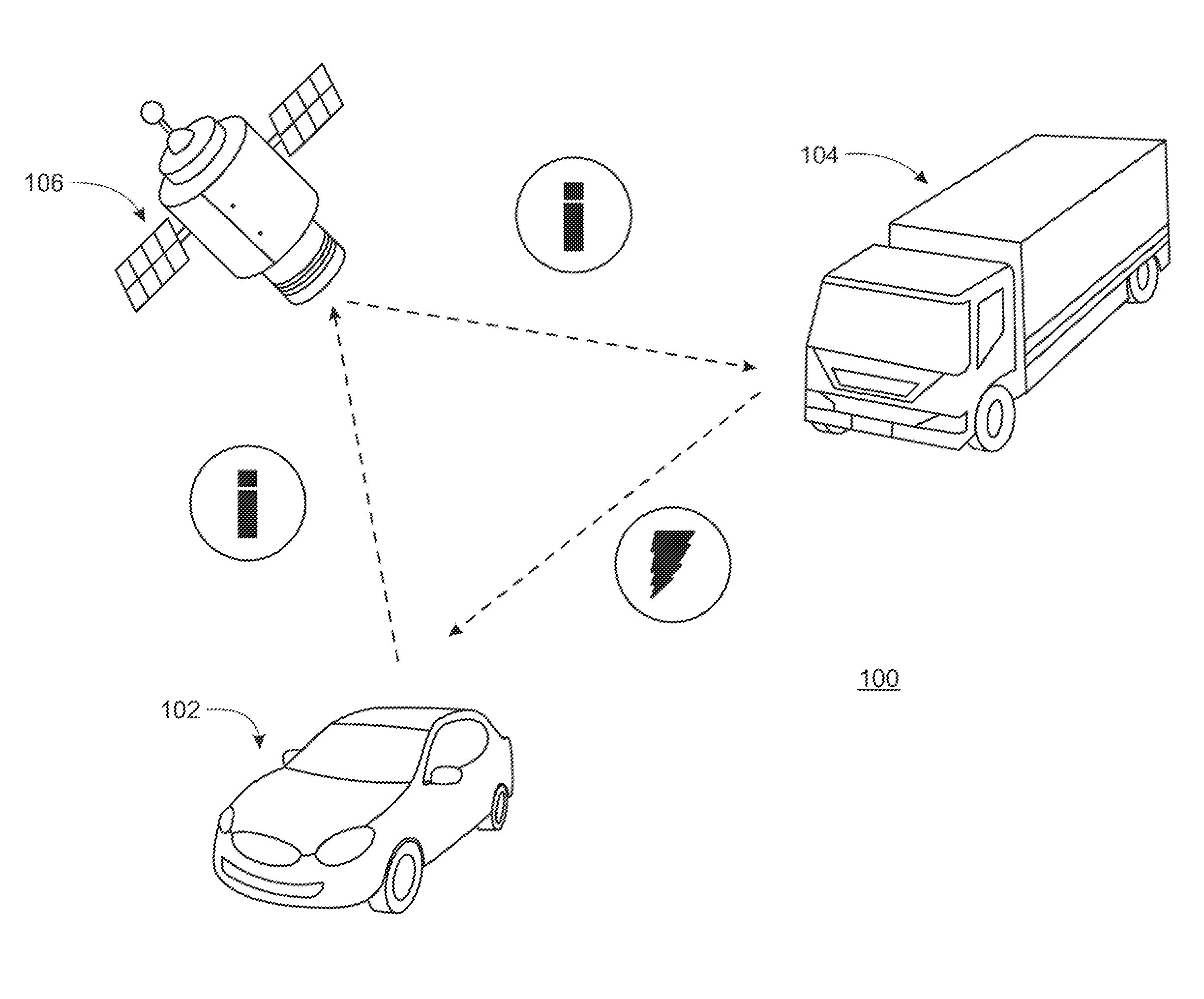
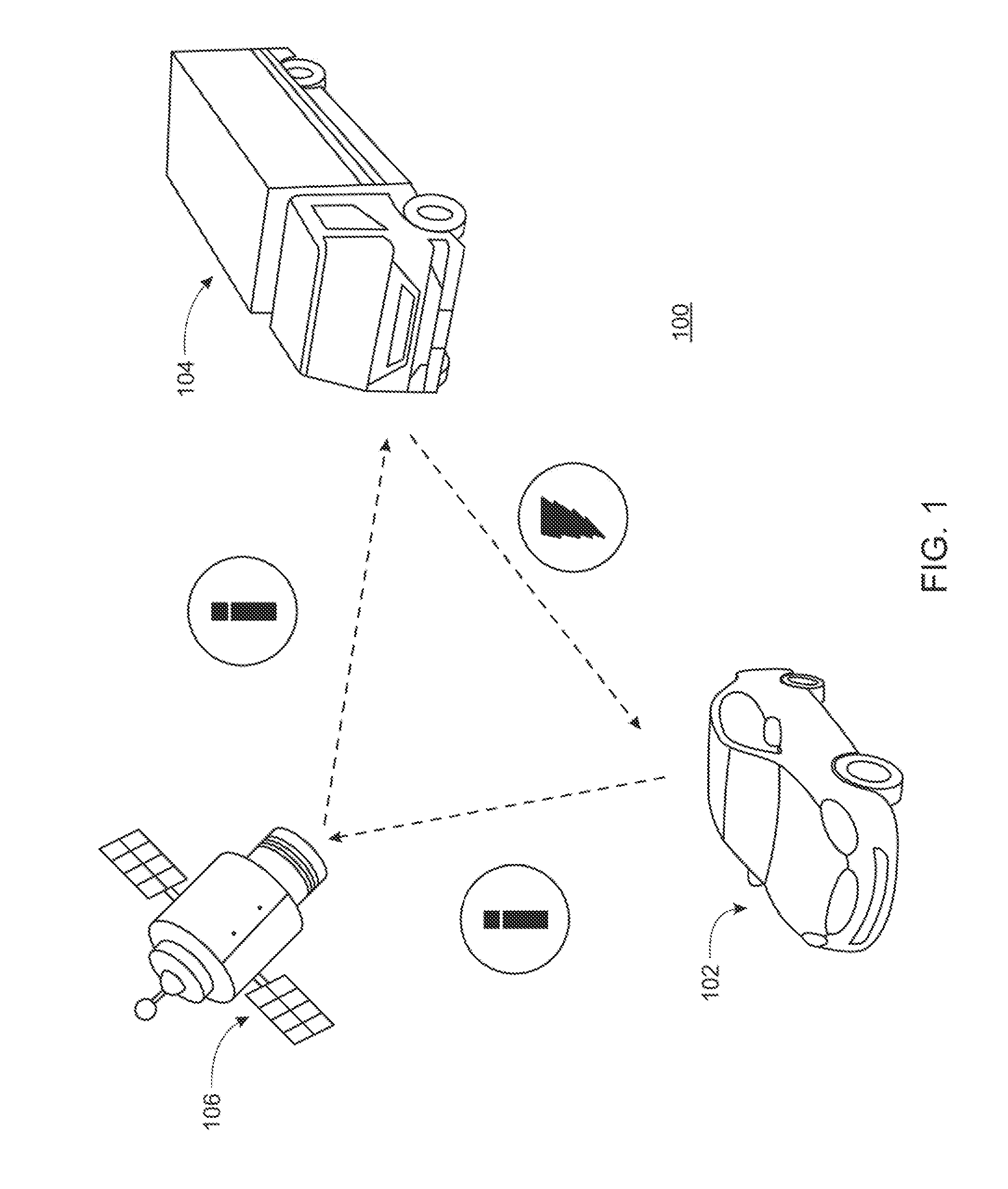
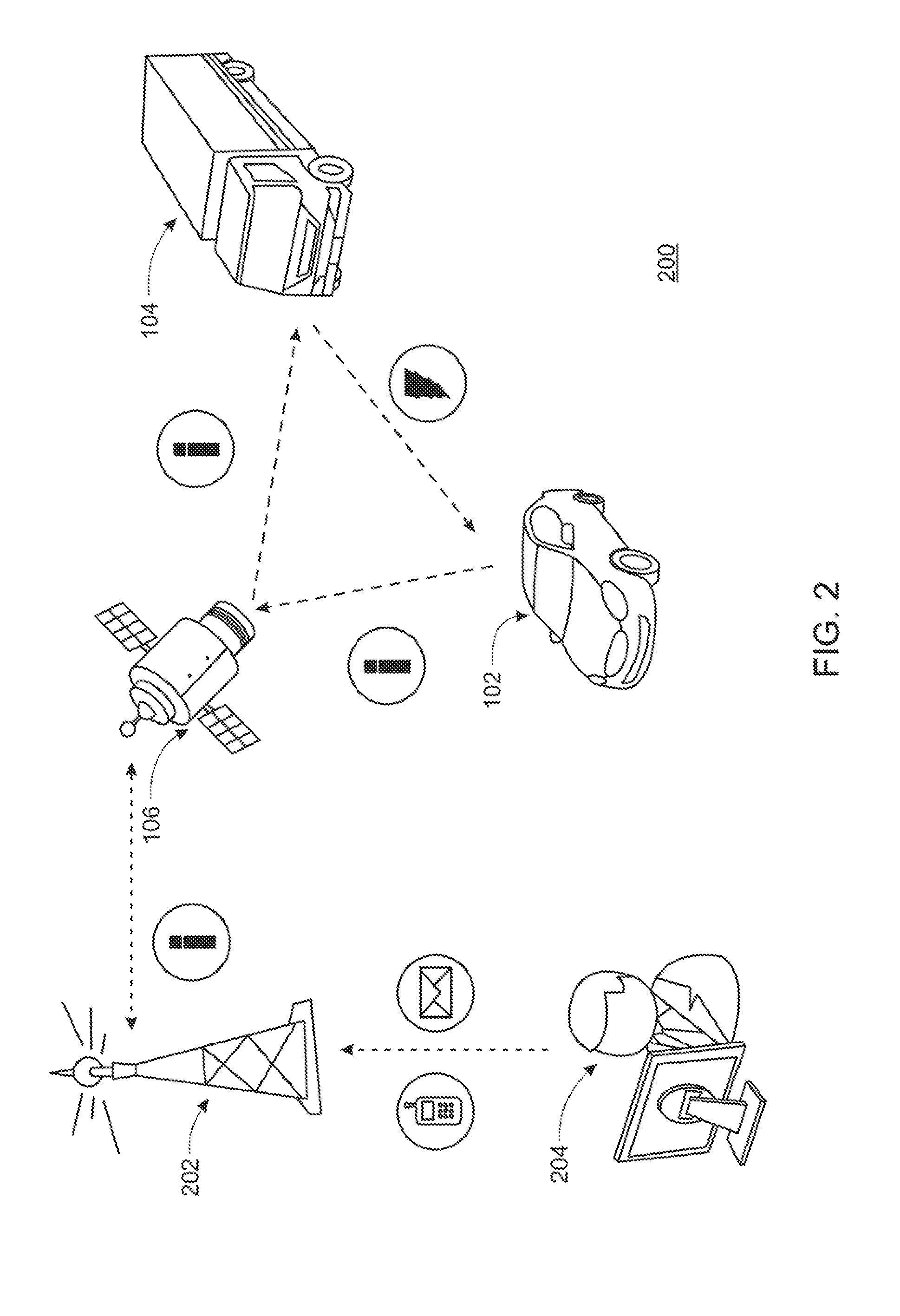
The present invention is about a system for charging electric vehicles. The system includes a charging device that connects to the electric vehicle and charges its battery. The charging device is connected to a network that can communicate with the electric vehicle. The network can send and receive communication from a central database. The electric vehicle requests a charge from the charging device through the network. The charging device is a mobile charging device that has its own battery with a higher potential than the battery in the electric vehicle. The charging device can be a vehicle or a charging vehicle. The system also includes a communication device that communicates with the network to receive charging requests. The charging device can be connected to a vehicle or be stationary. The charging device can be charged by a generator, such as a Stirling generator. The technical effects of this invention include improved charging efficiency and convenience for electric vehicles.

Problems solved by technology

However, many of these methods and devices require access to a particular connector which, in many cases, is electrically connected to a grid or power source.
Further, many of these devices require a specific connector which may not be universal.
With respect to at least partially electric vehicles, recharging may be difficult for the at least one battery may require a recharge in a location where a recharging device is not available.

Method used


Image

  • Systems, methods and apparatus for vehicle battery charging
  • Systems, methods and apparatus for vehicle battery charging
  • Systems, methods and apparatus for vehicle battery charging

Examples


Embodiment Construction

Definitions

[0026]As used in this description, drawings, and the accompanying claims, the following terms shall have the meanings indicated, unless the context otherwise requires:

[0027]A “vehicle” may include any means in or by which someone travels or something is carried or conveyed, or a conveyance moving on wheels, runners, tracks, treads, skis, arcuate elements, ground-contacting members, or the like. A vehicle may also include a watercraft, an aircraft or anything that is supported for flight in the air by buoyancy or by the dynamic action of air on its surfaces. A vehicle may also be propelled or pulled by something or someone.

[0028]A “charging vehicle” may be any type of vehicle capable of providing energy.

[0029]A “charging device” or “charging station” may be stationary, parked, mobile (such as a portable trailer or a pod), wireless, i.e., inductively coupled, or through a microwave laser beam, charged particle beams, or any other apparatus or device capable of providing ene...


PUM


Abstract

A system for charging a battery within an at least partially electric vehicle. The system includes a charging device wherein the charging device configured to electrically connect to the at least partially electric vehicle and charge at least one battery by a predetermined amount. The system also includes a network configured to determine the location of the charging device.

Description

CROSS REFERENCE TO RELATED APPLICATIONS[0001]The present application is a Non-Provisional Application which claims the benefit of U.S. Provisional Patent Application Ser. No. 61 / 230,210, filed Jul. 31, 2009 and entitled Method, System and Apparatus for Vehicle Battery Charging (Attorney Docket No. F69), which is hereby incorporated herein by reference in its entirety.TECHNICAL FIELD[0002]The present disclosure relates to one or more vehicle battery and more particularly, to systems, methods, and apparatus for vehicle battery charging.BACKGROUND INFORMATION[0003]Various devices and / or vehicles are powered by at least one battery. In some cases, the at least one battery is a battery capable of being recharged, sometimes referred to as a rechargeable battery. There are various methods and devices that may be used to recharge a battery. However, many of these methods and devices require access to a particular connector which, in many cases, is electrically connected to a grid or power s...

Claims


Application Information

Patent Timeline
Patent Type & Authority Applications(United States)
IPC IPC(8): H02J7/00
CPCB60L8/003B60L2250/16G06Q30/08G07F15/003H02J7/0027B60L2200/26H02J7/0055Y02T10/7055Y02T10/7083B60L11/1816B60L11/1848H02J7/0054B60L2240/70Y02T90/16Y02T10/7072Y02T90/14Y04S10/126Y04S30/14B60L55/00B60L53/65B60L53/665B60L58/12B60L2240/80H02J2207/40H02J7/342B60L53/305Y02E60/00Y02T10/70Y02T10/72Y02T90/12Y02T90/167H02J2310/48Y04S50/10H02J7/00045H02J7/0045B60L53/00B60L53/30
Inventor KAMEN, DEANHEINZMANN, RICHARD KURTSACHS, JASON M.
Owner DEKA PROD LLP
Learn More