Thermal head and printer

a printer and thermal head technology, applied in printing and other directions, can solve the problems of reducing the accuracy of measuring the thickness of the upper plate substrate, and the measurement of the thickness of the outer edge portion of the substrate, so as to improve the thermal efficiency of the thermal head, reduce the amount of printing energy, and improve the effect of thermal efficiency

Inactive Publication Date: 2011-02-03
SEIKO INSTR INC
View PDF8 Cites 6 Cited by
  • Summary
  • Abstract
  • Description
  • Claims
  • Application Information

AI Technical Summary

Benefits of technology

[0023]The printer includes the thermal head described above, and therefore it is possible to adjust the thickness of the upper plate substrate to an appropriate value to ensure the strength thereof, improve the thermal efficiency of the thermal head, and reduce the amount of energy required for printing.
[0024]According to the present invention, the effect is achieved that, even when the upper plate substrate and the lower plate substrate are in a bonded state, thermal efficiency may be improved by adjusting the thickness of the upper plate substrate to an appropriate value.

Problems solved by technology

Accordingly, variations in the thickness of the lower plate substrate are involved in the thickness of the upper plate substrate to be measured, which results in a problem of a reduction in accuracy of measuring the thickness of the upper plate substrate.
In addition, the thickness is measured with a measurement device by pinching an outer edge portion of the substrate including the upper and lower plate substrates bonded together, and hence a problem arises that only the thickness of the outer edge portion of the substrate may be measured.

Method used


Image

  • Thermal head and printer
  • Thermal head and printer
  • Thermal head and printer

Examples


first embodiment

[0043]Referring to the drawings, a thermal head 1 and a thermal printer 10 according to a first embodiment of the present invention are described.

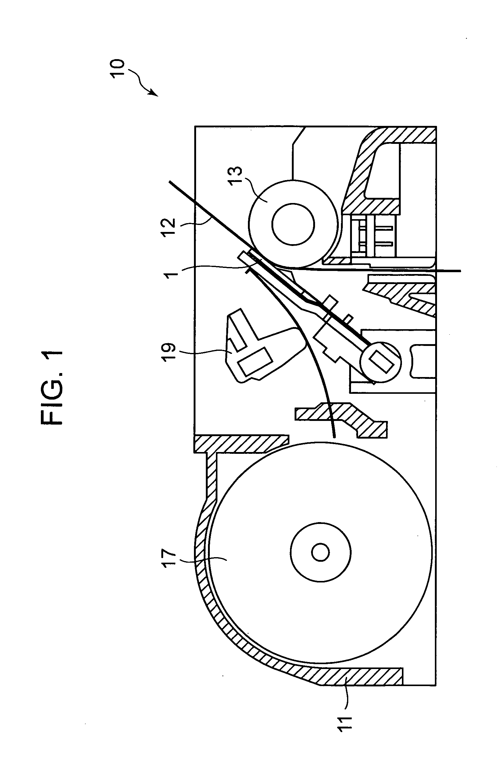
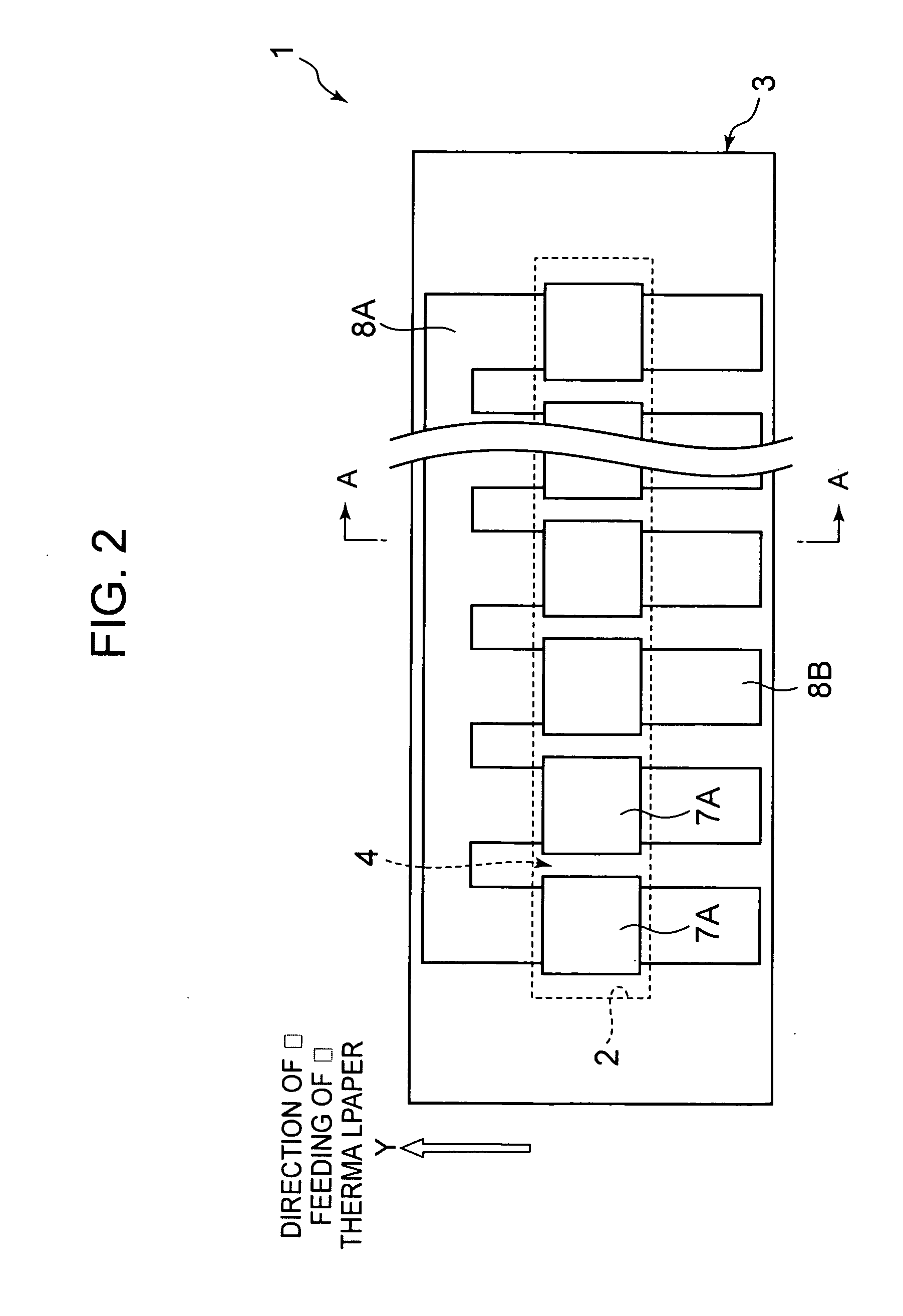
[0044]The thermal head 1 according to this embodiment is used in the thermal printer 10 as illustrated in, for example, FIG. 1, and selectively drives a plurality of heating elements based on printing data to effect printing onto a printing target such as thermal paper 12 or the like.

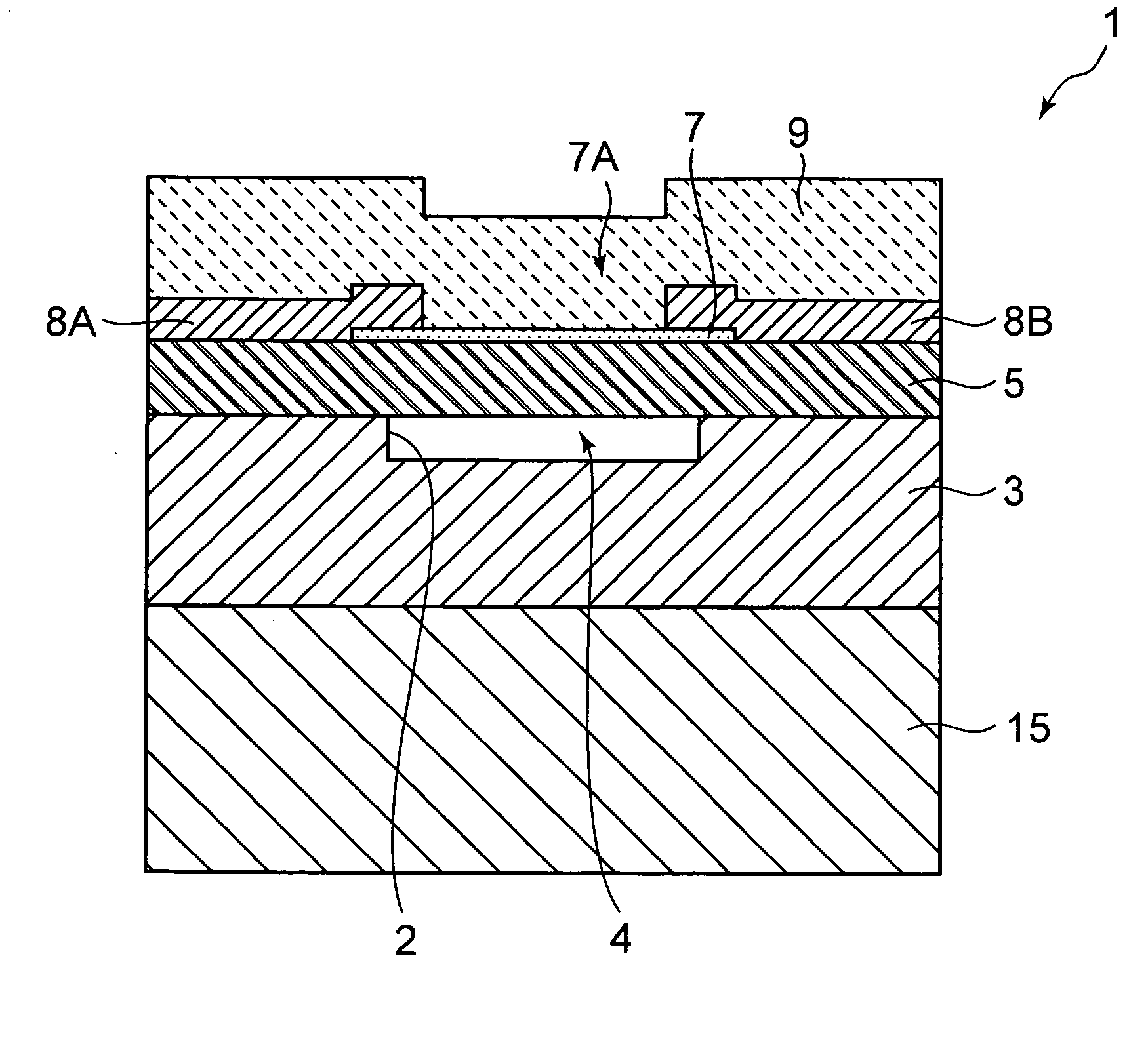
[0045]The thermal printer 10 includes a main body frame 11, a platen roller 13 disposed horizontally, the thermal head 1 disposed oppositely to an outer peripheral surface of the platen roller 13, a heat dissipation plate 15 (see FIG. 3) supporting the thermal head 1, a paper feeding mechanism 17 for feeding the thermal paper 12 between the platen roller 13 and the thermal head 1, and a pressure mechanism 19 for pressing the thermal head 1 against the thermal paper 12 with a predetermined pressing force.

[0046]Against the platen roller 13, the thermal head 1 an...

second embodiment

[0084]A second embodiment of the present invention is described hereinbelow. Note that, in the second and subsequent embodiments, a description of matters common to the embodiment described above is omitted, and different matters are mainly described.

[0085]As illustrated in FIG. 11, in a thermal head 1 according to this embodiment, through holes 23 passing through the upper plate substrate 5 in the plate thickness direction are provided in four corners of the upper plate substrate 5. Similarly to the through holes 21 described above, the through holes 23 pass through the upper plate substrate 5 from the top surface thereof to the top surface of the support substrate 3, and are used to align the support substrate 3 with the upper plate substrate 5 when the support substrate 3 and the upper plate substrate 5 are to be bonded together.

[0086]In the top surface of the support substrate 3, cavities (marks) 25 for alignment are provided at positions corresponding to the through holes 23, a...

third embodiment

[0089]A third embodiment of the present invention is described hereinbelow.

[0090]As illustrated in FIGS. 13A and 13B, in a thermal head 1 according to this embodiment, in the upper plate substrate 5, air vents 28 passing through the upper plate substrate 5 in the plate thickness direction are provided at positions other than those of the thermal heads 1. On the other hand, in the top surface of the support substrate 3, grooves 29 are formed at positions corresponding to the air vents 28 of the upper plate substrate 5.

[0091]As illustrated in FIGS. 14A and 14B, the conventional thermal head has a problem that air bubbles (voids) 31 are formed between the support substrate 3 and the upper plate substrate 5 to degrade the adhesion between the support substrate 3 and the upper plate substrate 5. Conventionally, when the support substrate 3 and the upper plate substrate 5 are bonded together, the bonding is performed stepwise by pressing the support substrate 3 and the upper plate substra...


PUM


Abstract

Provided is a thermal head in which, even when an upper plate substrate and a lower plate substrate are in a bonded state, a thickness of the upper plate substrate is adjusted to an appropriate value to allow an improvement in thermal efficiency. Adopted is a thermal head including: a support substrate; an upper plate substrate having a back surface thereof bonded to a top surface of the support substrate; a heating resistor provided on the upper plate substrate; a concave portion formed in a region of at least one of the top surface of the support substrate and the back surface of the upper plate substrate, which opposes the heating resistor; and a through portion formed in the upper plate substrate, which passes through the upper plate substrate from a top surface of the upper plate substrate to the top surface of the support substrate in a plate thickness direction.

Description

BACKGROUND OF THE INVENTION[0001]1. Field of the Invention[0002]The present invention relates to a thermal head and a printer including the thermal head.[0003]2. Description of the Related Art[0004]There has been conventionally known a thermal head used in a thermal printer to effect printing onto a thermosensitive recording medium by selectively driving a plurality of heating elements based on printing data (see, for example, patent document JP 2007-83532 A).[0005]As a method for achieving a reduction in power consumption by improving thermal efficiency of a heating resistor in a thermal head, there has been known a method in which a hollow portion is formed in a region opposing the heating resistor. By allowing the hollow portion to function as a heat insulating layer having a low thermal conductivity, and reducing an amount of heat propagated and dissipated from the heating resistor to a support substrate, efficiency of energy used for printing may be improved.[0006]Such a therma...

Claims


Application Information

Patent Timeline
Patent Type & Authority Applications(United States)
IPC IPC(8): B41J2/335
CPCB41J2/3359B41J2/3355
Inventor SANBONGI, NORIMITSU
Owner SEIKO INSTR INC
Why Eureka
Try Eureka