Liquid crystal display device
a display device and liquid crystal technology, applied in non-linear optics, instruments, optics, etc., can solve the problems of reduced transmissivity increase in the cost of manufacture of the display device, and inevitability of multi-layer arrangement, so as to prevent other people. the effect of preventing other peopl
- Summary
- Abstract
- Description
- Claims
- Application Information
AI Technical Summary
Benefits of technology
Problems solved by technology
Method used
Image

Examples
embodiment 1
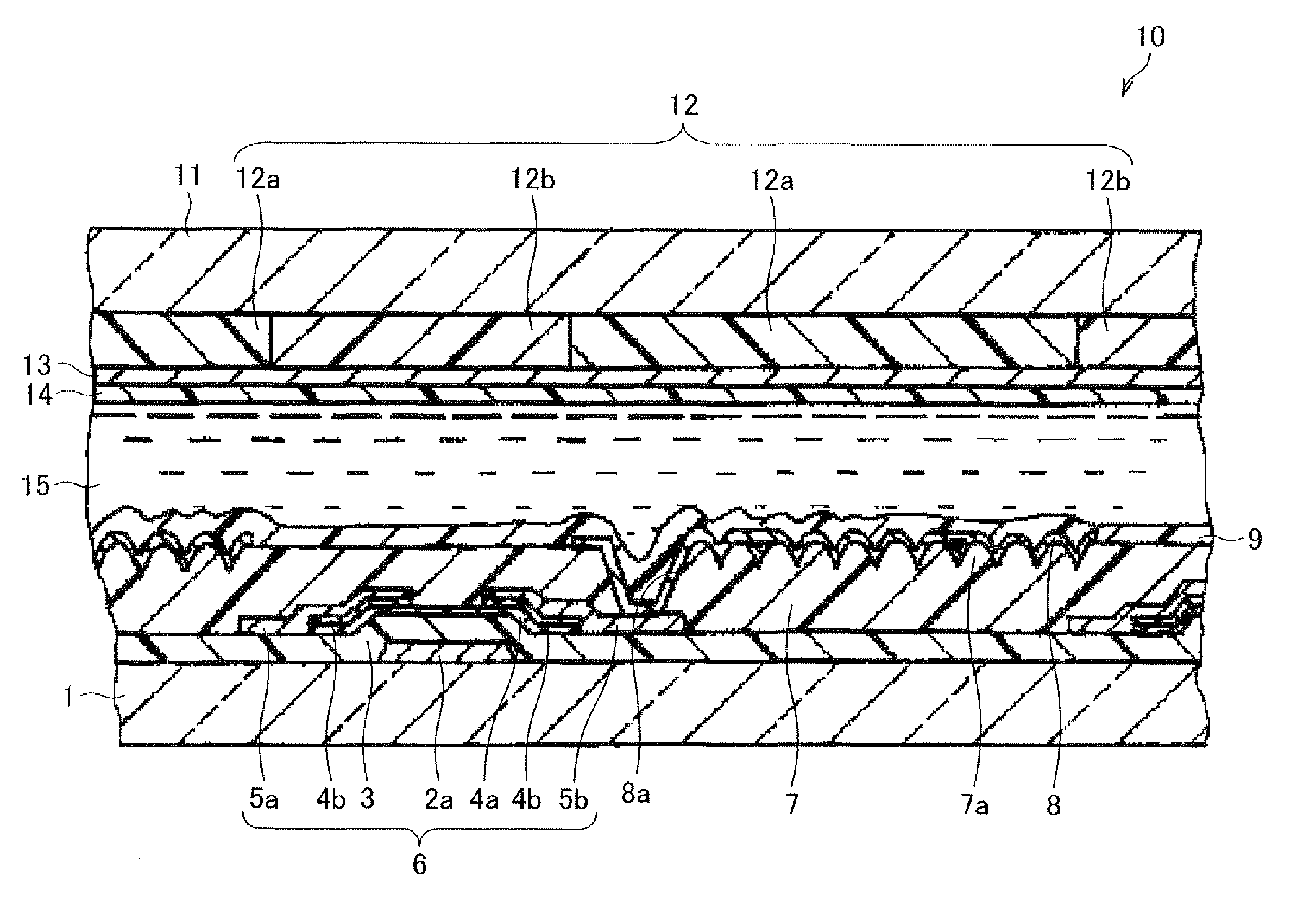
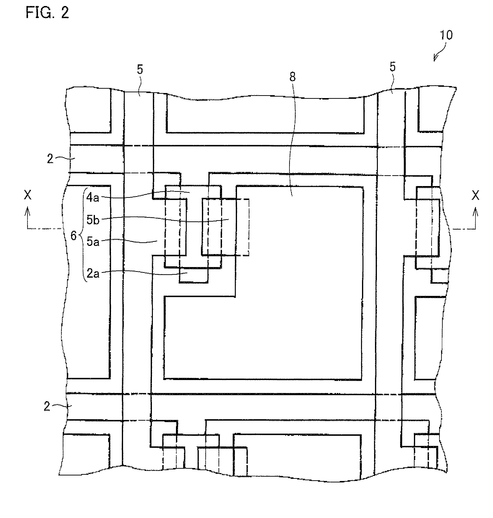
[0100]An embodiment of the present invention is described below with reference to FIGS. 1 through 13, and FIG. 19. Each of drawings referenced below illustrates only main members necessary to explain the present invention, among members of the embodiment of the present invention, for the sake of simple explanation. Therefore, a liquid crystal display device of the present invention may include other members which are not illustrated in the drawings referenced in the present specification. Further, each member in the drawings is not exactly identical with an actual component in size, dimensional ratio of the actual components, etc.
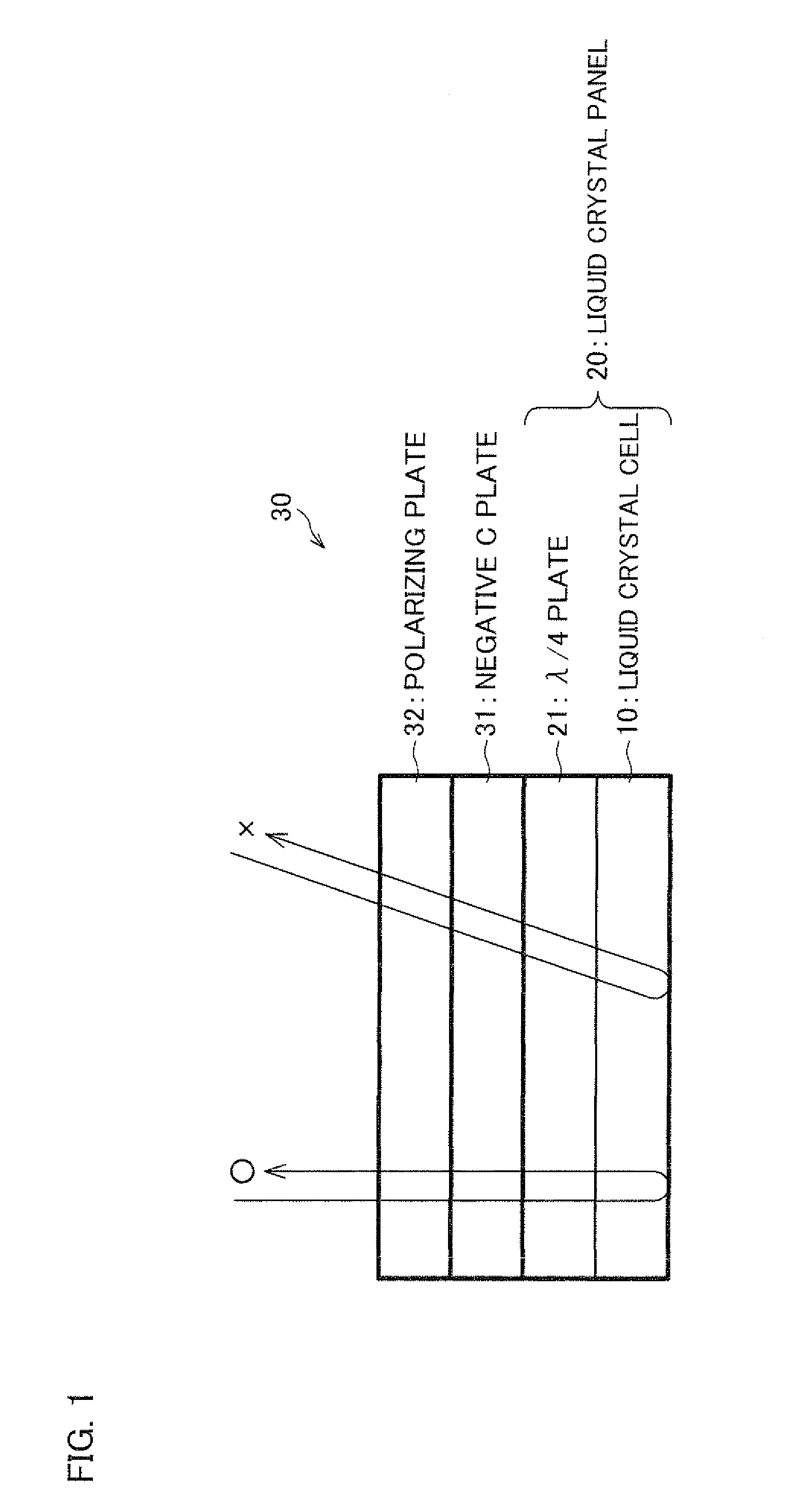
[0101]First, the following description deals with an arrangement of a liquid crystal display device 30 of the present embodiment with reference to FIG. 1. FIG. 1 is a cross-sectional view schematically illustrating the arrangement of the liquid crystal display device 30.
[0102]The liquid crystal display device 30 is a reflective liquid crystal display device...
embodiment 2
[0166]The following description deals with another embodiment of the present invention with reference to FIGS. 14 through 17. Note that the arrangements other than the arrangement described in the present embodiment are the same as in Embodiment 1. Further, the members having the same functions as the members illustrated in the drawings used in Embodiment 1 have the same signs, and explanations of these are omitted for the sake of simple explanation.
[0167]As illustrated in FIG. 14A, a liquid crystal display device 40 of the present embodiment includes a positive C plate 41 (second phase plate) in place of the negative C plate 31 of the liquid crystal display device 30 of Embodiment 1.
[0168]That is, the positive C plate 41 is a phase plate which (i) has three principal refractive indexes nx in the x axis direction, ny in the y axis direction, and nz in the z axis direction, which directions are orthogonal to each other, and (ii) has a relationship of “nx=ny41 of the present embodimen...
embodiment 3
[0187]The following description deals with still another embodiment of the present invention with reference to FIG. 18. Note that the arrangements other than the arrangement described in the present embodiment are the same as in Embodiment 1. Further, the members having the same functions as the members illustrated in the drawings used in Embodiment 1 and Embodiment 2 have the same signs, and explanations of these are omitted for the sake of simple explanation.
[0188]As illustrated in (a) through (e) of FIG. 18, a liquid crystal display device of the present embodiment includes a positive A plate (nx>ny=nz), a negative A plate (nz=nx>ny), an X plate (nx>ny>nz), or the like (each of which functions as the phase difference member (the phase plate)), in place of the negative C plate 31 of the liquid crystal display device 30 of Embodiment 1 or the positive C plate 41 of Embodiment 2.
[0189]Further, these various phase plates are arranged so that the direction of either the nx axis or the...
PUM
 Abstract
Description
Claims
Application Information
 - R&D
- Intellectual Property
- Life Sciences
- Materials
- Tech Scout
- Unparalleled Data Quality
- Higher Quality Content
- 60% Fewer Hallucinations
Browse by: Latest US Patents, China's latest patents, Technical Efficacy Thesaurus, Application Domain, Technology Topic, Popular Technical Reports.
© 2025 PatSnap. All rights reserved.Legal|Privacy policy|Modern Slavery Act Transparency Statement|Sitemap|About US| Contact US: help@patsnap.com