Lidar Measurement Device for Vehicular Traffic Surveillance and Method for Use of Same

a technology of vehicular traffic and measurement device, which is applied in the direction of measurement device, speed/acceleration/shock measurement, instruments, etc., can solve the problems of restricting its effectiveness and use in highway safety programs, affecting the detection of positive operator target identification, and the use of lidar speed-measuring devices that do not operate on doppler radar principles

Active Publication Date: 2011-02-03
APPLIED CONCEPTS
View PDF9 Cites 35 Cited by
  • Summary
  • Abstract
  • Description
  • Claims
  • Application Information

AI Technical Summary

Benefits of technology

[0006]The teachings presented herein address the aforementioned limitations by providing precise aiming of the Lidar to track moving vehicles in a multiple vehicle environment without the need for existing awkward accessories or positions causing human fatigue. In particular, tripods are avoided and it is not necessary to maintain the butt end of the stock of the Lidar against the shoulder. Rather, by using a steerable laser, which may, for example, be mounted to a police vehicle, the laser beam may be scanned horizontally and vertically in a step-wise manner to paint a picture of the targets present within the field of view being captured by the video circuitry. The processing capabilities of the Lidar measurement device correlate the target data, such as range, direction of heading, and speed, to the video image for positive target identification by law enforcement or another user of the Lidar measurement device.

Problems solved by technology

Limitations, however, have led to restricting its effectiveness and use in highway-safety programs.
As a result, positive operator target identification is perceived as challenging.
Lidar speed-measuring devices do not operate on Doppler radar principles.
But, while Lidar overcomes certain specific limitations associated with radar speed-measurement devices, it introduces challenges of its own.
Both methods make use more cumbersome than that of Doppler radar speed-measuring devices.

Method used


Image

  • Lidar Measurement Device for Vehicular Traffic Surveillance and Method for Use of Same
  • Lidar Measurement Device for Vehicular Traffic Surveillance and Method for Use of Same
  • Lidar Measurement Device for Vehicular Traffic Surveillance and Method for Use of Same

Examples


Embodiment Construction

[0014]While the making and using of various embodiments of the present invention are discussed in detail below, it should be appreciated that the present invention provides many applicable inventive concepts which can be embodied in a wide variety of specific contexts. The specific embodiments discussed herein are merely illustrative of specific ways to make and use the invention, and do not delimit the scope of the present invention.

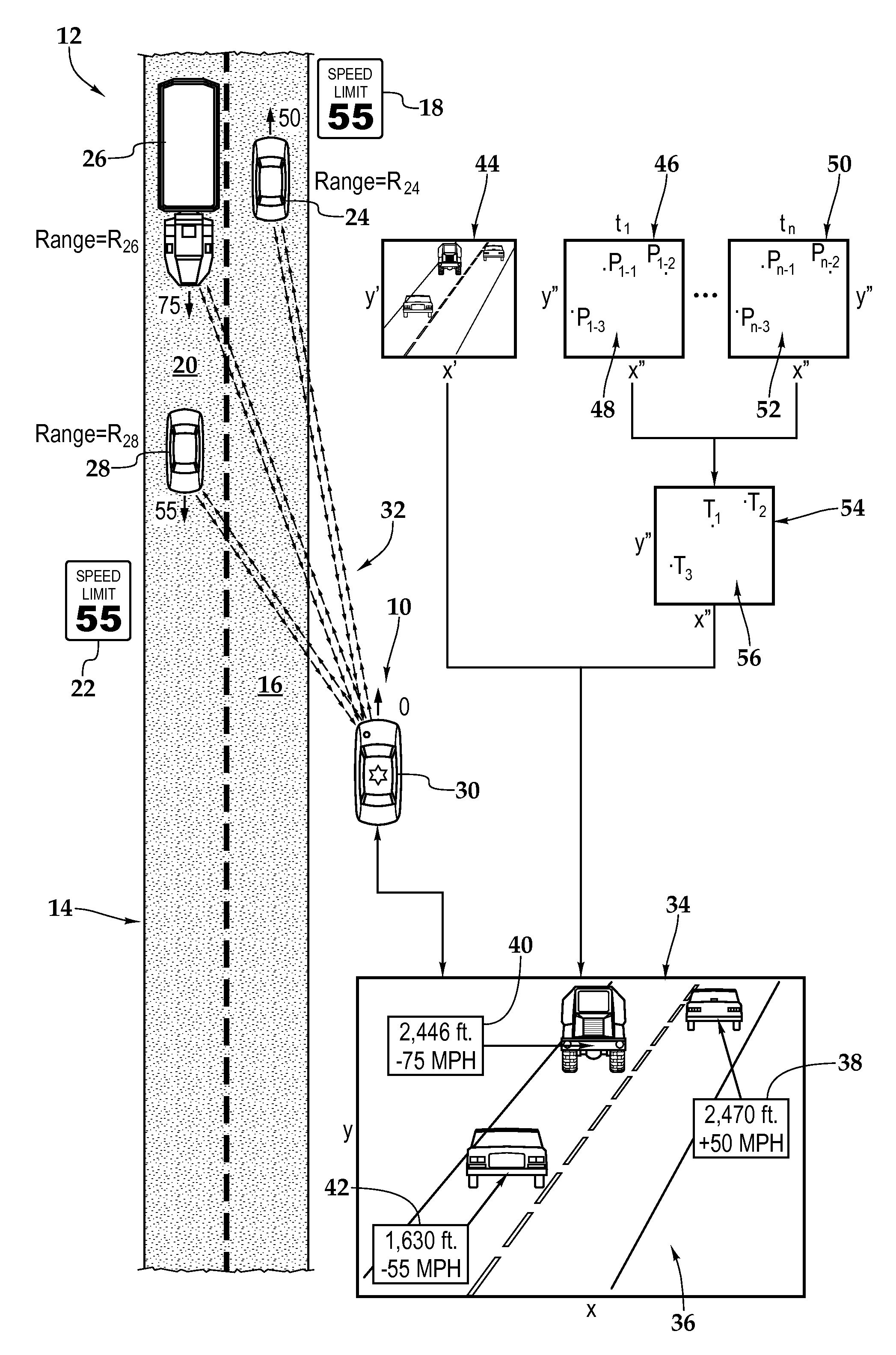
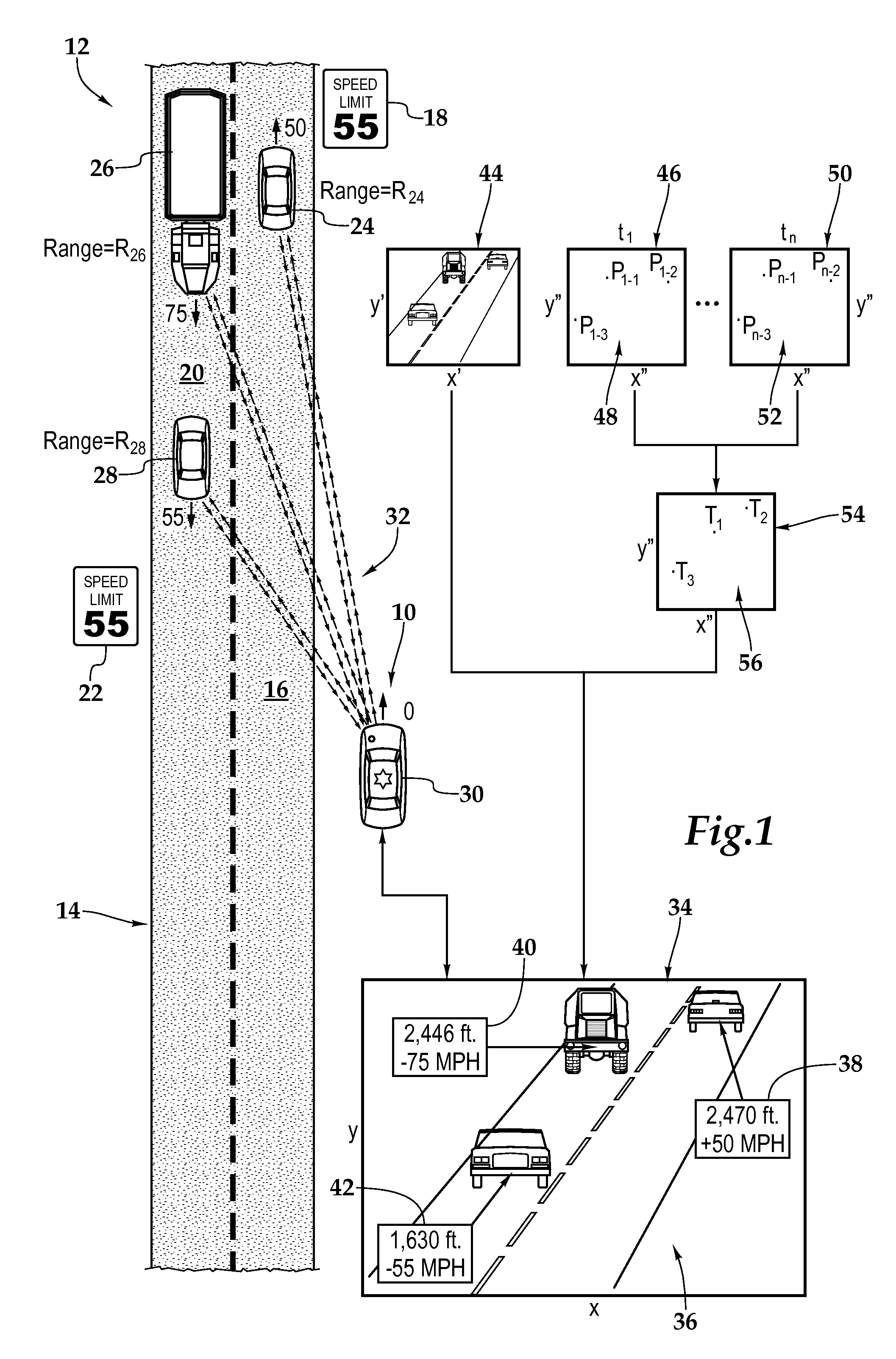
[0015]Referring initially to FIG. 1, therein is depicted one embodiment of a Lidar measurement device, which is schematically illustrated and generally designated 10, being utilized in a multiple vehicle environment 12. A highway 14 includes a northbound lane 16 having a speed limit of 55 mph as depicted by speed limit sign 18 and a southbound lane 20 having a speed limit of 55 mph as depicted by speed limit sign 22. A vehicle 24 is traveling in the northbound lane 16 at a speed of 50 mph as indicated by the northbound arrow and number “50” proximate to...


PUM


Abstract

A Lidar measurement device for vehicular traffic surveillance and method for use of same are disclosed. In one embodiment, video circuitry acquires video of a field of view having a target therein. A steerable laser progressively transmits laser range-finding signals to the field of view in a horizontal and vertical step-wise manner and receives reflected laser range-finding signals from the target. A processing circuit portion determines target data of the target based upon range and time measurements associated with the reflected laser range-finding signals. The processing circuit then integrates the target data into the video such that the video may displayed with an image of the target and speed measurement associated therewith.

Description

PRIORITY STATEMENT & CROSS-REFERENCE TO RELATED APPLICATIONS[0001]This application discloses subject matter related to the subject matter disclosed in the following commonly owned, co-pending patent application: “Lidar Measurement Device with Target Tacking and Method for Use of Same,” filed on ______1 application Ser. No. ______ (Attorney Docket No.: 1005.1037), in the name of Robert S. Gammenthaler; which is hereby incorporated by reference for all purposes.TECHNICAL FIELD OF THE INVENTION[0002]This invention relates, in general, to police speed detection systems and, in particular, to a light detection and ranging (Lidar) measurement device for vehicular traffic surveillance in environments having multiple target vehicles and a method for use of the same.BACKGROUND OF THE INVENTION[0003]The role of speed detection in traffic safety enforcement is widespread throughout the United States and the principal tool for police traffic surveillance is Doppler radar. In a police Doppler ra...

Claims


Application Information

Patent Timeline
Patent Type & Authority Applications(United States)
IPC IPC(8): G01P3/36G01S17/86G01S17/89
CPCG01S17/023G01S17/42G01S17/89G01S17/88G01S17/58G01S17/86
Inventor GAMMENTHALER, ROBERT S.
Owner APPLIED CONCEPTS
Why Eureka
Try Eureka