
Packet Switch with Separate Look Ahead, Computation, and Shift Phases

a packet switch and look-forward technology, applied in the field of packet switches, can solve the problems of reducing the routing speed of optical packet switches, and the general inability of optical packet switches to achieve the same level of throughput performan

Inactive Publication Date: 2011-02-03
UNIV OF SOUTHERN CALIFORNIA
View PDF1 Cites 2 Cited by
  • Summary
  • Abstract
  • Description
  • Claims
  • Application Information

AI Technical Summary

Benefits of technology

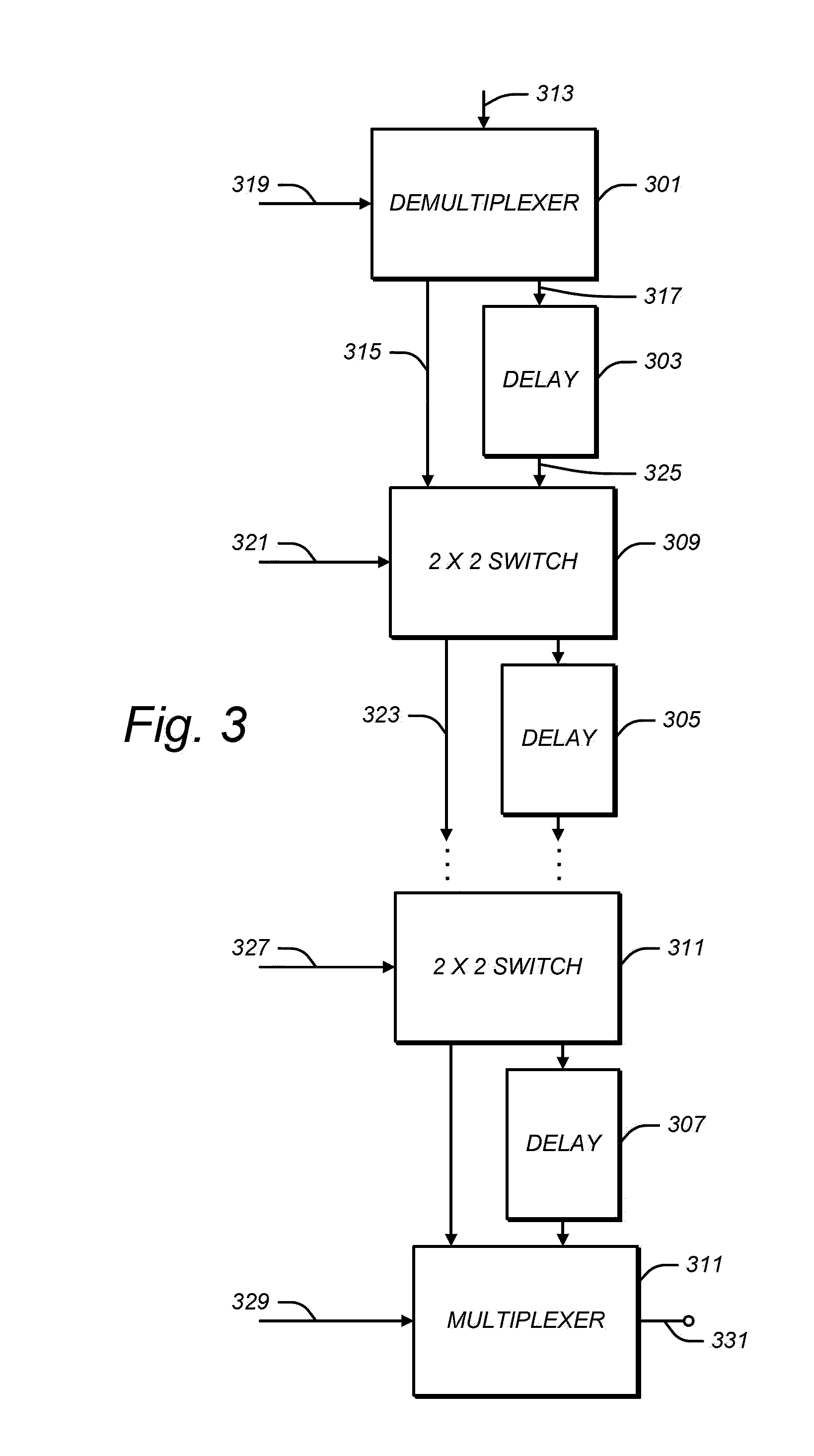
[0021]When determining each output sequence, each programmable delay line controller may be configured to give weight to achieving the lowest possible average output delay, the lowest possible loss of packets, and / or prioritizing information.

Problems solved by technology

Although optical packets can be converted to electronic packets and then buffered by random-access buffers, this can slow down the routing of the optical packets substantially.
Without buffers, moreover, optical packet switches have generally not been able to achieve the same level of throughput performance as electronic ones.

Method used


Image

  • Packet Switch with Separate Look Ahead, Computation, and Shift Phases
  • Packet Switch with Separate Look Ahead, Computation, and Shift Phases
  • Packet Switch with Separate Look Ahead, Computation, and Shift Phases

Examples


Embodiment Construction

[0039]Illustrative embodiments are now discussed. Other embodiments may be used in addition or instead. Details which may be apparent or unnecessary may be omitted to save space or for a more effective presentation. Conversely, some embodiments may be practiced without all of the details which are disclosed.

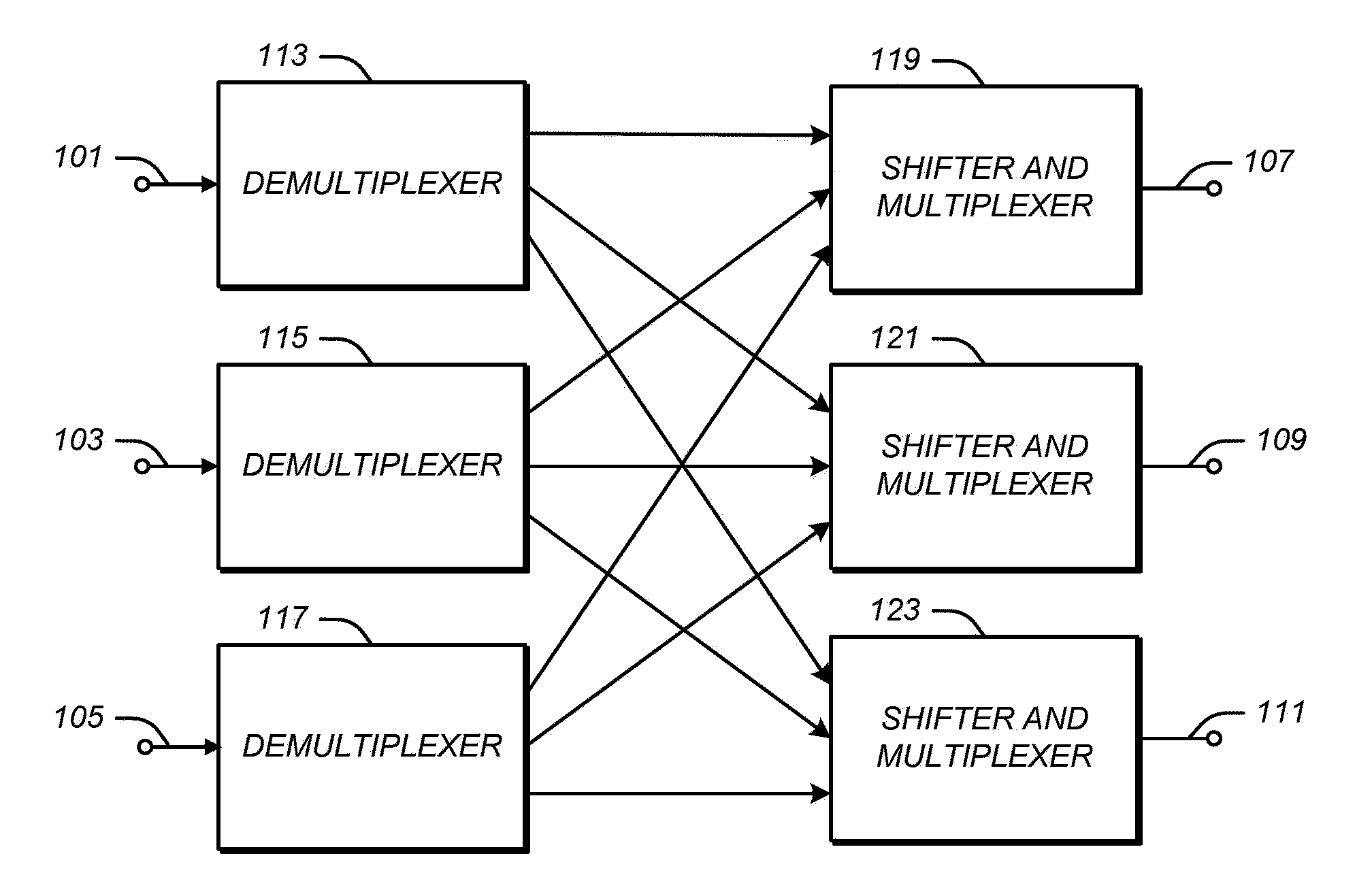
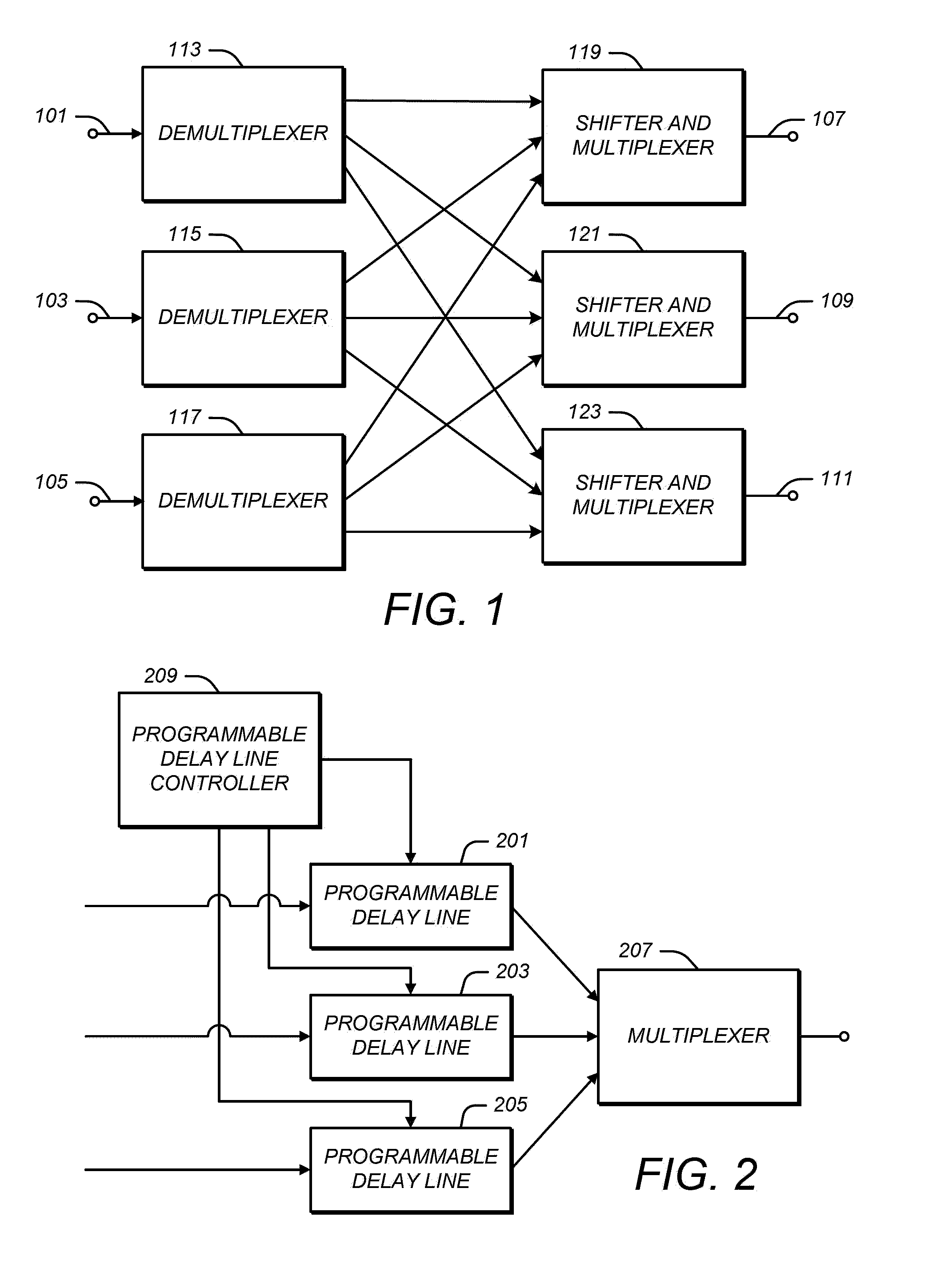
[0040]FIG. 1 illustrates a packet switch. As illustrated in FIG. 1, the packet switch may include a plurality of input ports, such as input port 101, 103, and 105. Each may be configured to receive one or more packets containing data and / or other information. Although only three input ports are illustrated in FIG. 1, the packet switch may have a different number, such as two, four, five, or any other number.

[0041]The packet switch may include a plurality of output ports, such as output port 107, 109, and 111. Each may be configured to deliver one or more of the packets. Although only three output ports are illustrated in FIG. 1, a different number may be used, such as one, two, f...


PUM


Abstract

A packet switch architecture that can switch optical packets at high throughputs without using any random access memory, without fragmenting variable length packets into fixed length fragments and reassembling them, and without converting the optical packets into electronic packets. Programmable delay lines are use which delay the output of each packet for a programmable amount which may be re-programmed while the packet is being delayed by the programmable delay line. Programmable delay line controllers manages the delays imposed by the programmable delay lines so as to have a look-ahead phase during which information about the packets is gathered and a shift phase during which the sequence of packets is shifted to match an output sequence.

Description

CROSS-REFERENCE TO RELATED APPLICATION[0001]This application is based upon and claims priority to U.S. provisional patent application 61 / 229,635, entitled “Packet Switch Using First-In First-Out Queues,” filed Jul. 29, 2009, attorney docket number 028080-0489, the entire content of which is incorporated herein by reference.STATEMENT REGARDING FEDERALLY SPONSORED RESEARCH[0002]This invention was made with Government support under Contract No. CNS-0626788 awarded by the National Science Foundation; under Contract No. N66001-02-1-8939 awarded by Defense Advanced Research Projects Agency (DARPA); and under Contract No. CNS-0812072 awarded by the National Science Foundation. The Government has certain rights in the invention.BACKGROUND[0003]1. Technical Field[0004]This disclosure relates to packet switches for network systems, including packet switches which switch optical packets.[0005]2. Description of Related Art[0006]Packet switches commonly receive streams of packets on several diff...

Claims


Application Information

Patent Timeline
Patent Type & Authority Applications(United States)
IPC IPC(8): H04L12/56
CPCH04Q11/0005H04Q11/0066H04L49/109H04Q2011/005H04L49/102H04Q2011/002
Inventor TOUCH, JOSEPH D.BANNISTER, JOSEPHSURYAPUTRA, STEPHEN
Owner UNIV OF SOUTHERN CALIFORNIA
Learn More