
Imaging apparatus and control method thereof

Inactive Publication Date: 2011-02-03
CANON KK
View PDF4 Cites 21 Cited by
  • Summary
  • Abstract
  • Description
  • Claims
  • Application Information

AI Technical Summary

Benefits of technology

[0016]The present invention can provide the display which is con

Problems solved by technology

However, the apparatus as mentioned above has the following problems: As for capturing the subject P, in the fluoroscope process of positioning the objective portion to be captured, a wide region and low X-ray amount are desirable and a resolution and frame rate may be compromised in some degree.
However, in such capture, there is a problem in that the operation becomes complicated due to the condition of X-ray irradiation, the setting of X-ray aperture and the setting of binning having to be performed independently.
Further, there is the problem that it is difficult to immediately determine whether or not the binning setting should be changed using the image information displayed on the monitor.

Method used


Image

  • Imaging apparatus and control method thereof
  • Imaging apparatus and control method thereof
  • Imaging apparatus and control method thereof

Examples


first embodiment

[0032]First, why capture conditions have to be determined considering priority of image or priority of frame rate as shown in this embodiment will be described.

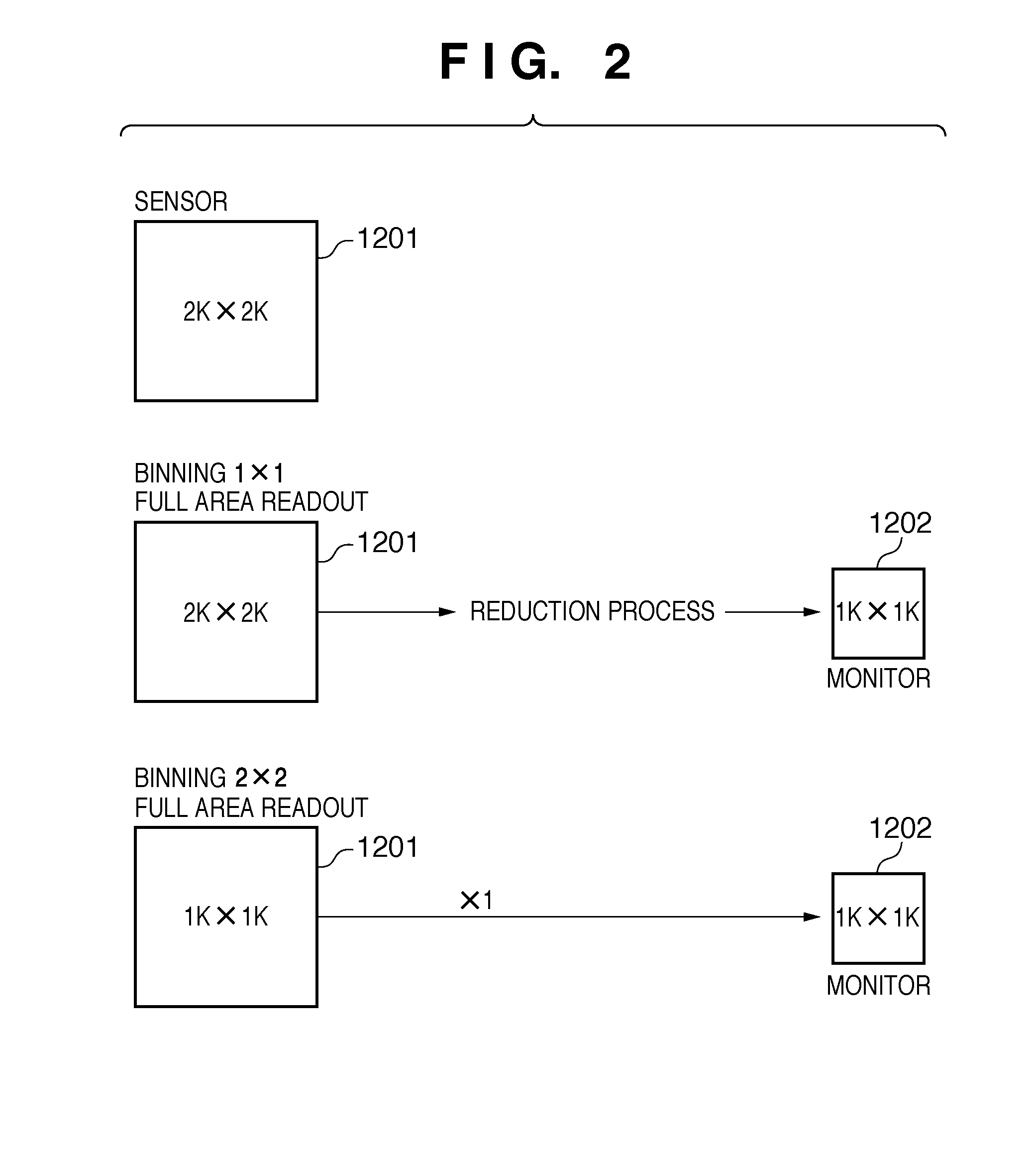
[0033]FIG. 2 illustrates general relationship between an image display and image interpolation. As shown in FIG. 2, a pixel size of a sensor 1201 is assumed 2K×2K, and a pixel size of a monitor 1202 is assumed 1K×1K. In this case, for example, if an image is captured with the high resolution of binning 1×1, then the image cannot be displayed on the monitor unless the reduction process is applied as shown in FIG. 2. This reducing process will degrade the image quality with the interpolation. So, the image will have to be captured again. This will be an image capture by wasting the X-ray irradiating dose. Thus, even if the image is captured with a high resolution, the image cannot be displayed with the resolution higher than the monitor's resolution. Therefore, the image should be captured with the resolution considering a disp...


PUM


Abstract

An imaging apparatus having an X-ray detector and an image display unit comprises first and second display magnification calculation units and a selection unit. The first display magnification calculation unit receives information of the detected image size, a binning condition and a display frame size, and thereby calculating a first display magnification so as to maximize a display area of the detected image. The second display magnification calculation unit temporarily changes the received binning condition, and by using the temporarily changed binning condition and the received detected image size, and calculates a second display magnification so as to maximize a display area. The selection unit selects the first display magnifications and the temporarily change binning condition if the first display magnification is closer to one and the second display magnification with one.

Description

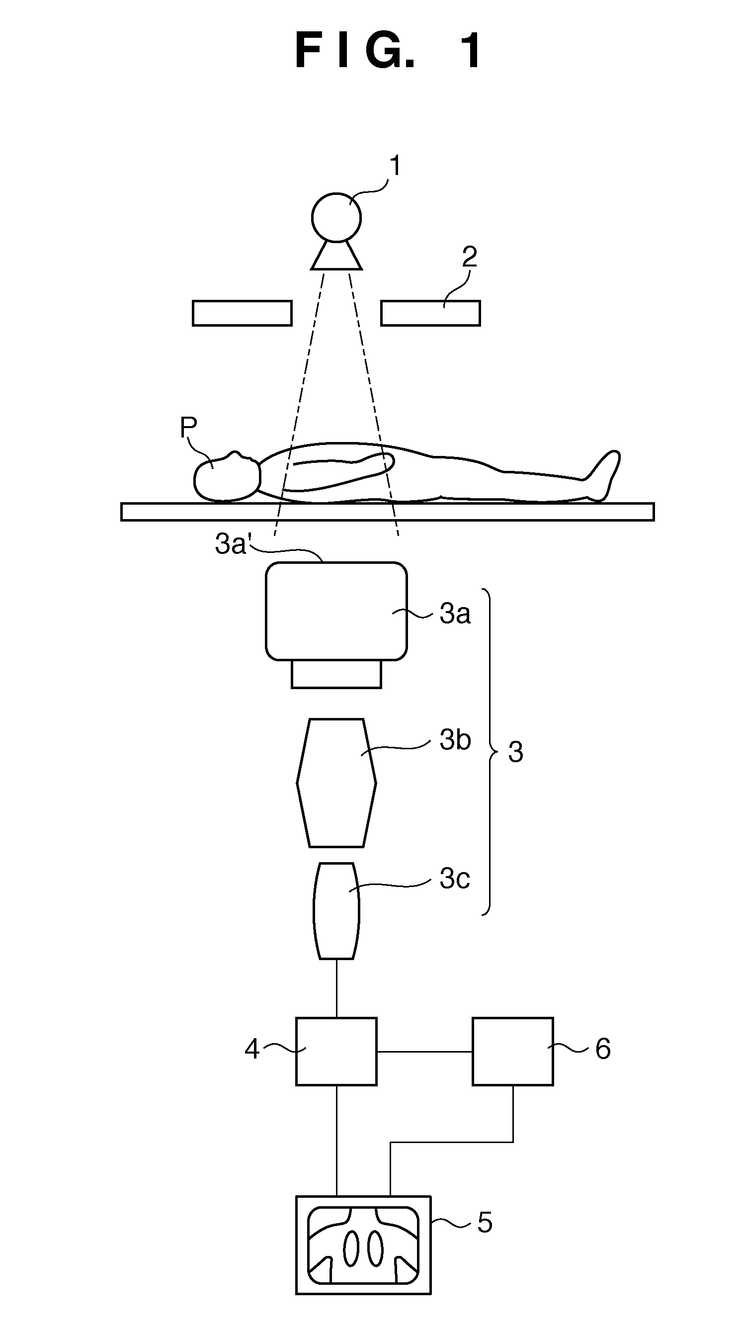
BACKGROUND OF THE INVENTION[0001]1. Field of the Invention[0002]The present invention relates to a medical X-ray imaging apparatus.[0003]2. Description of the Related Art[0004]An image intensifier-TV system is especially utilized for fluoroscopic radiography apparatus in the area of diagnostic imaging using a medical X-ray image capture apparatus.[0005]FIG. 1 illustrates an example of an image intensifier (hereafter “I.I”)-TV system in the past. First, X-ray from an X-ray tube 11be is irradiated to a subject P through an X-ray aperture 2. Then, the transmission X-ray transmitted through the subject P is detected by a detection unit 3, converted to an image signal, and the converted image signal is displayed as an image on a monitor 5 via an image processing means 4.[0006]The X-ray irradiated to the subject P is placed via the X-ray aperture 2 so as to irradiate only a predetermined region that is required for capturing an image. The detection unit 3 converts the transmission X-ray t...

Claims


Application Information

Patent Timeline
IPC IPC(8): H05G1/64G09G5/00
CPCA61B6/06A61B6/4233A61B6/487A61B6/5205G09G2380/08G06F3/14G09G5/005G09G2340/04G09G2340/0435A61B6/58
Inventor TAKEKOSHI, KOJI
Owner CANON KK
Learn More